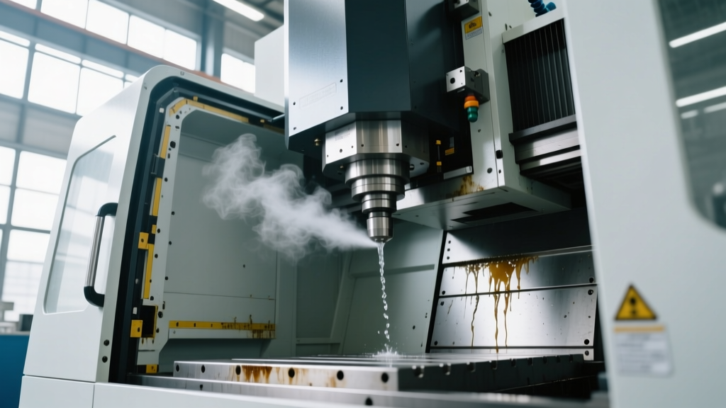
Mastering Spindle Speed and Feed Rate Optimization on Any NC and CNC Machine
Learn the exact physics, formulas, and material-specific parameters to optimize spindle speed and feed rate on any NC and CNC machine for maximum tool life.
The Physics of Cutting: Surface Speed vs. Spindle RPM
Optimizing tool life and surface finish requires a fundamental understanding of the relationship between cutting speed and spindle rotation. Many operators mistakenly treat Spindle Speed (RPM) and Surface Speed (SFM or m/min) as interchangeable. They are not. Surface speed ($V_c$) is the linear velocity at which the cutting edge engages the workpiece material. Spindle speed ($N$) is simply the rotational output required to achieve that surface speed for a specific tool diameter.
Core Optimization Formulas
Imperial (Inches): $N = \frac{V_c \times 12}{\pi \times D}$
Metric (Millimeters): $N = \frac{V_c \times 1000}{\pi \times D}$
Feed Rate ($V_f$): $V_f = N \times z \times f_z$
Where $D$ = Cutter Diameter, $z$ = Number of flutes, and $f_z$ = Chip load per tooth (IPT or mm/tooth).
If you run a 0.500-inch endmill and a 1.000-inch endmill at the exact same RPM in 6061-T6 aluminum, the larger tool is cutting at twice the surface speed. This leads to immediate thermal degradation of the carbide substrate on the larger tool. Always calculate RPM based on the desired surface speed for the specific material and tool diameter. For authoritative baseline surface speeds, refer to the Harvey Tool Speeds and Feeds Guide.
Radial Chip Thinning: The Hidden Feed Rate Killer
One of the most critical, yet frequently overlooked, concepts in modern milling is Radial Chip Thinning (RCT). When your Radial Depth of Cut (RDOC) is less than 50% of the tool's diameter, the chip formed is physically thinner than the actual distance the tool advances per tooth.
If you program a standard chip load of 0.003 inches per tooth (IPT) but only engage 10% of the tool diameter (a common practice in trochoidal or dynamic milling paths in Mastercam 2026 or Fusion 360), your effective chip thickness drops to approximately 0.001 inches. This causes the cutting edge to rub rather than shear, generating massive friction heat and leading to premature edge wear or work hardening in materials like 304 stainless steel or Inconel 718.
Expert Rule of Thumb: When RDOC is less than 50% of the tool diameter, you must mathematically increase your programmed feed rate to maintain the minimum required chip thickness for proper heat evacuation. Use the RCT formula: $f_{z(actual)} = \frac{f_{z(desired)}}{\sqrt{1 - (\frac{RDOC}{Radius})^2}}$.
Material-Specific Speed and Feed Matrix
The following matrix provides baseline parameters for 3-flute and 4-flute solid carbide endmills utilizing AlTiN or ZrN coatings. These values assume a rigid setup with minimal overhang (less than 3x diameter stickout) and flood coolant or high-pressure through-tool coolant.
| Material | Tool Type / Flutes | Diameter | Surface Speed (SFM) | Spindle Speed (RPM) | Chip Load (IPT) | Feed Rate (IPM) |
|---|---|---|---|---|---|---|
| 6061-T6 Aluminum | 3-Flute Carbide | 0.500" | 2,000 | 15,278 | 0.003" | 137 |
| 304 Stainless Steel | 4-Flute Carbide | 0.500" | 300 | 2,291 | 0.002" | 18 |
| Ti-6Al-4V (Titanium) | 5-Flute Carbide | 0.500" | 150 | 1,145 | 0.0015" | 8.5 |
| P20 Tool Steel | 4-Flute Carbide | 0.500" | 350 | 2,673 | 0.002" | 21 |
For precise metric conversions and advanced threading calculations, the Kennametal Machining Calculators provide excellent shop-floor reference tools.
Execution Differences: Legacy NC vs. Modern CNC Machine Controllers
When evaluating the kinematic differences between an older NC and CNC machine setup, understanding how the controller processes feed and speed commands is critical for avoiding scrapped parts and broken tooling.
Legacy NC Machine Limitations
Older Numerical Control (NC) machines, utilizing hardwired logic or early softwired tape readers, execute G-code strictly block-by-block. They lack processing memory for upcoming path geometry. If a toolpath requires a sharp 90-degree corner deceleration, an NC machine will physically slow the axes to near-zero to make the directional change. However, the spindle RPM remains entirely constant. This results in the tool 'dwelling' in the corner, rubbing the material, causing severe work hardening (especially in austenitic stainless steels), and generating localized thermal shock that fractures the carbide cutting edge.
Modern CNC Machine Look-Ahead and Adaptive Control
Modern Computer Numerical Control (CNC) machines, equipped with 2026-era controllers like the Fanuc Series 31i-B5 or Siemens Sinumerik One, utilize Nanometer-level look-ahead, processing 1,000 to 2,000 blocks ahead of the current position. When approaching a corner or a tight radius, the CNC controller dynamically adjusts axis feed rates to maintain a constant centrifugal force limit, preventing the tool from being pulled out of the cut. Furthermore, AI-driven adaptive control features (such as Siemens' OptiTurn or Fanuc's Intelligent Spindle Load Control) can micro-adjust the spindle speed override in real-time based on spindle motor amperage, ensuring the chip load remains constant even during heavy engagement transitions.
Real-World Troubleshooting: Acoustic and Visual Diagnostics
Optimization is rarely perfect on the first program run. Use these acoustic and visual diagnostics to tune the setup at the machine pendant:
- High-Pitch Squeal (Regenerative Chatter): This indicates harmonic vibration between the tool and workpiece. Fix: Do not simply slow down. Alter the spindle RPM by 10-15% (up or down) to break the harmonic frequency, or increase the feed rate by 20% to force the tool through the material rather than bouncing off it.
- Low-Pitch Rumble (Tool Deflection): The radial forces are exceeding the tool's rigidity, pushing it away from the cut. Fix: Reduce the Radial Depth of Cut (RDOC) to 5-7% of the tool diameter for finishing passes, and compensate by increasing the Axial Depth of Cut (ADOC) to maintain material removal rates.
- Blue/Purple Chips in Steel or Titanium: This is actually a good sign in roughing. It indicates that the heat is being carried away by the chip rather than transferred into the tool or workpiece. If chips are silver or bright yellow, your surface speed is too low or your chip load is too thin.
- Built-Up Edge (BUE) on Aluminum: Material is welding to the cutting edge, eventually snapping off and taking carbide with it. Fix: Increase spindle speed, ensure you are using a polished-flute uncoated or ZrN coated tool, and verify your flood coolant concentration is at least 8-10% to provide adequate lubricity.
Step-by-Step Tuning Protocol for New Setups
Follow this exact sequence when proving out a new toolpath to ensure optimal spindle and feed parameters:
- Calculate Baselines: Use the Sandvik Coromant Formulas and Definitions to calculate your theoretical RPM and IPM based on the tool manufacturer's recommended surface speed and chip load.
- Apply the 80% Rule for Proving: Program the initial run at 80% of the calculated feed rate and 100% of the calculated spindle speed. Keep the spindle speed override switch at 100% to maintain proper surface footage.
- Monitor Spindle Load Meter: Watch the machine's spindle load meter during the heaviest cut. For roughing, target 60-75% continuous load. If it spikes above 85%, reduce the RDOC or feed rate.
- Inspect the First 10 Parts: Check the cutting edges under a 10x loupe. Look for flank wear (normal, gradual wear land) versus crater wear or edge chipping (indicates excessive heat or shock, requiring speed/feed adjustments).
- Push to Optimization: Once the process is stable, increase the feed rate in 5% increments until surface finish degrades or chatter begins, then back off by one increment. This establishes your absolute maximum efficient feed rate for production.