Reviewing CNC Machine Photos Images for Enclosure Leak Repair
Learn how to analyze CNC machine photos images to diagnose enclosure seal failures, coolant leaks, and misting issues with remote visual troubleshooting.
The Visual Diagnostic Matrix for Remote Troubleshooting
In modern manufacturing environments, remote diagnostics has shifted from a luxury to a baseline operational requirement. When floor operators submit visual documentation of equipment faults, maintenance engineers must extract maximum data from minimal context. Reviewing submitted CNC machine photos images allows off-site technicians to triage enclosure breaches, coolant system failures, and seal degradations before ever stepping onto the shop floor. However, visual evidence is only as valuable as the diagnostic framework applied to it.
Below is a primary diagnostic matrix used to map visual cues found in operator-submitted imagery to specific enclosure and coolant system failures.
| Visual Symptom in Imagery | Probable Root Cause | Component to Inspect | Estimated Repair Cost |
|---|---|---|---|
| Milky residue on way cover bellows | Tramp oil infiltration / Emulsion breakdown | Coolant skimmer, way lube lines | $450 - $1,200 |
| Micro-tears at polyurethane wiper edges | Chip packing and UV/thermal degradation | Way cover wipers, telescopic seals | $150 - $400 per axis |
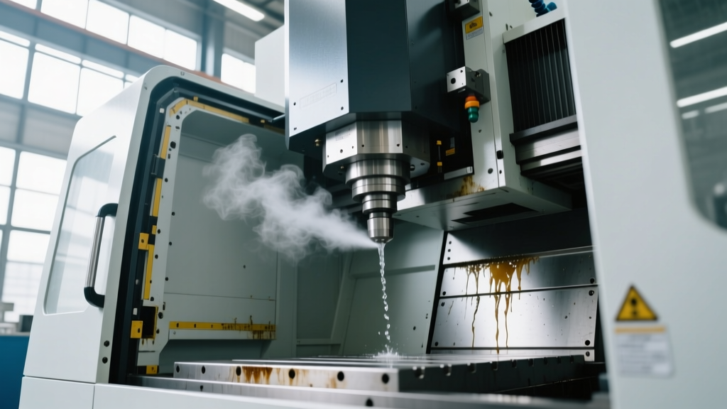
| Aerosolized mist escaping door seams | Positive pressure buildup / Gasket compression set | Door extrusions, enclosure ventilation | $200 - $850 |
| Cavitation pitting on coolant nozzle tips | Flow restriction / Pump starvation | Suction filters, impeller housing | $300 - $1,500 |
Decoding Enclosure Seal Failures from Visual Evidence
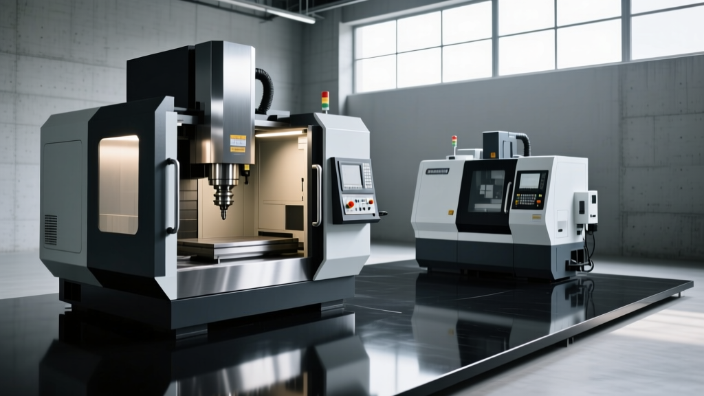
Enclosure systems on high-speed machining centers—such as the Haas VF-2SS or DMG MORI NLX series—are subjected to extreme thermal cycling and high-velocity chip impacts. When analyzing CNC machine photos images of enclosure faults, technicians must look beyond obvious puddles and focus on material deformation and micro-ingress points.
Way Cover Bellows and Wiper Degradation
Way covers protect precision linear guideways and ball screws from abrasive swarf. In submitted imagery, look closely at the interface between the polyurethane wiper and the machine casting. If the photos reveal a 'lip' or curling at the wiper edge, the material has suffered compression set and lost its memory. This is common in standard nitrile rubber (NBR) wipers exposed to synthetic coolants exceeding 140°F (60°C). Upgrading to Fluorocarbon (Viton) wipers with a 70A Shore hardness rating resolves this thermal degradation, though it increases part costs by approximately 40%.
Warning: Never rely solely on wide-angle photos for way cover inspections. Operators must provide macro shots (within 6 inches) of the bellow folds. Chip fines (cast iron or titanium) often lodge deep in the folds, acting as a grinding compound that destroys the linear guide blocks from the inside out.Door Gasket Extrusion and Compression Set
Machine doors utilize continuous extruded rubber seals to contain coolant splash and aerosolized mist. A common failure mode visible in close-up imagery is 'extrusion'—where the gasket material appears squished or flattened outward from its retaining channel. This indicates that the door hinges have sagged, misaligning the latch mechanism and forcing the seal against the frame at an uneven angle. If the CNC machine photos images show asymmetric gasket compression, the repair requires realigning the door hinges (typically adjusting the M12 hinge bolts by 1-2mm) rather than simply replacing the seal.
Coolant System Anomalies: Spotting the Unseen
Coolant systems are the lifeblood of the cutting process, managing thermal expansion and lubricating the shear zone. Visual troubleshooting of these systems requires understanding fluid dynamics and chemical stability.
Tramp Oil and Emulsion Instability
When operators photograph the coolant sump, maintenance teams should look for the 'sheen effect.' A rainbow-like sheen on the fluid surface indicates tramp oil (way lube or hydraulic fluid) has breached the sump and is not being adequately skimmed. According to guidelines published by the National Institute for Occupational Safety and Health (NIOSH), unstable emulsions caused by tramp oil not only degrade tool life but increase the risk of operator respiratory issues due to altered misting properties. If the sump photos show heavy oil pooling, the immediate action is to deploy a coalescing oil skimmer and verify that the way lube metering resistance valves are not stuck open.
Nozzle Cavitation and Misting Patterns
High-pressure coolant-through (HPTC) systems operate at 1,000 to 2,000 PSI. A highly effective trick for diagnosing HPTC faults via imagery is the 'flash photography' method. By instructing the operator to take a photo of the cutting zone with the camera flash enabled, technicians can illuminate aerosolized coolant mist that is invisible to the naked eye. If the flash reveals a chaotic, asymmetrical misting pattern rather than a tight, focused cone, the nozzle is experiencing cavitation or partial blockage from swarf. This requires flushing the spindle union and inspecting the 40-micron inline filters.
'A well-lit macro photograph of a coolant nozzle tip can reveal cavitation pitting that indicates a failing pump impeller weeks before the system throws a low-pressure alarm.' — Senior Fluid Systems Engineer, Advanced Manufacturing Diagnostics
Standardized Workflow for Capturing Diagnostic Imagery
To ensure the CNC machine photos images submitted by floor staff are actionable, maintenance departments must enforce a standardized capture workflow. Vague, poorly lit photos lead to misdiagnosed parts orders and extended downtime.
- Context Shot (Wide): Capture the entire machine enclosure with the door open to establish the general location of the leak or fault.
- Source Tracking (Medium): Photograph the fluid path. Coolant obeys gravity; trace the wetness upward to find the highest point of origin.
- Component Macro (Close): Use the smartphone's macro mode or move within 4 inches of the suspected seal, wiper, or nozzle. Ensure the camera flash is ON to highlight micro-tears and fluid sheen.
- Operational State (Video/Action): If safe, capture a 5-second video of the enclosure while the spindle is running at 5,000 RPM to visualize misting patterns and dynamic seal failures that static photos miss.
Financial Impact of Ignored Visual Cues
Delaying repairs based on a 'quick visual check' that misses critical details carries severe financial penalties. A minor enclosure seal leak, if left unaddressed, allows coolant to migrate into the servo motor encoder housings. Replacing a single absolute encoder on a Fanuc or Siemens servo motor costs between $1,200 and $2,800, not including the 4-6 hours of downtime required for re-homing and ballbar calibration. Furthermore, the Occupational Safety and Health Administration (OSHA) strictly regulates worker exposure to metalworking fluid mists; an enclosure failing to contain aerosolized coolant can result in severe compliance citations and mandatory production halts.
Troubleshooting FAQ
How often should enclosure seals be visually inspected?
Operators should perform a basic visual check daily during the warm-up cycle. Maintenance teams should conduct a detailed photographic audit of all way covers, door gaskets, and sump seals every 500 operating hours, archiving the CNC machine photos images in the machine's CMMS (Computerized Maintenance Management System) to track degradation rates over time.
Can I use standard silicone sealant to patch a torn way cover bellow?
No. Standard silicone lacks the tensile strength and chemical resistance to withstand synthetic coolants and the mechanical stretching of the bellow. Use a specialized polyurethane adhesive or replace the bellow section entirely. Patching is only acceptable as a 24-hour emergency stopgap.
What causes coolant to foam excessively inside the enclosure?
Foaming is rarely a leak issue; it is a chemical one. It is typically caused by a coolant concentration that is too low (below 5%), high water hardness, or the introduction of air into the system via a suction leak on the pump inlet. Check the refractometer readings and inspect the pump intake O-rings.