Mastering 3-Axis CNC Machine India Setups: Operator Best Practices
Master 3-axis CNC machine setup in India's manufacturing sector. Learn operator best practices, tramming tolerances, and capability limits for job shops.
Operational Realities of 3-Axis VMCs in Indian Manufacturing
When deploying a 3-axis CNC machine, India's diverse industrial environments—from the high-humidity coastal belts of Chennai to the particulate-heavy zones of Manesar and Peenya—demand rigorous setup protocols. The Indian MSME (Micro, Small, and Medium Enterprises) job shop sector relies heavily on 3-axis Vertical Machining Centers (VMCs) for automotive sub-assemblies, die-mold bases, and general precision components. However, treating a VMC installation as a simple 'plug-and-play' operation leads to premature spindle bearing failure, geometric drift, and scrapped batches.
According to data from the Indian Machine Tool Manufacturers Association (IMTMA), domestic VMC consumption continues to surge, driven by the automotive and aerospace ancillary sectors. Yet, a significant percentage of machine downtime in Indian job shops is traced back to improper initial commissioning and environmental mismanagement rather than inherent machine defects.
Grid Volatility Warning: Industrial zones in India frequently experience 415V 3-phase fluctuations exceeding ±10%. Operating a VMC servo drive without a dedicated 1% regulation servo stabilizer will trigger Yaskawa or Fanuc over-voltage alarms and degrade the spindle drive's IGBT modules within 18 months. Always install an isolation transformer and servo stabilizer rated at 125% of the machine's maximum KVA draw.Core Capabilities and Market Benchmarks
The 3-axis VMC is the workhorse of Indian precision engineering. While 5-axis machines dominate complex aerospace contours, 3-axis platforms offer the rigidity, torque, and cost-efficiency required for high-volume prismatic parts. Below is a capability and pricing matrix for three dominant models in the Indian market as of 2026.
| Brand & Model | Spindle Taper | Max Spindle RPM | Rapid Traverse | Approx. 2026 Price (INR) |
|---|---|---|---|---|
| Ace Micromatic GX 350 | BT40 | 10,000 RPM | 36 m/min | ₹28,50,000 |
| Jyoti CNC KX 16 | BT40 | 12,000 RPM | 48 m/min | ₹32,00,000 |
| Haas VF-2 | BT40 | 8,100 RPM | 30.5 m/min | ₹46,00,000 |
Note: Pricing reflects base models with standard 24-tool ATC (Automatic Tool Changer) and excludes local taxes, installation, and third-party workholding.
Foundation and Installation: Mitigating Environmental Variables
The physical footprint of a 3-axis CNC machine in India requires more than a leveled concrete floor. Vibrations from nearby stamping presses, heavy vehicle traffic, or overhead cranes can transmit through the foundation, causing chatter marks on finished surfaces and accelerating ballscrew wear.
Phase 1: Foundation and Isolation Protocol
- Epoxy Grouting: Do not rely on standard cement pads. Use a high-modulus epoxy grout (e.g., MasterFlow 648) poured to a minimum depth of 50mm beneath the leveling pads to dampen high-frequency vibrations.
- Precision Leveling: Utilize a 0.02mm/m resolution machinist level. Level the machine in both X and Y axes before anchoring. Re-check 48 hours post-grouting to account for thermal settling and mechanical stress relaxation.
- Thermal Isolation: Ensure the machine is not placed in direct line with factory bay doors or exhaust fans. Ambient temperature swings exceeding 8°C within a 12-hour shift will cause the cast iron column to expand or contract, shifting the spindle centerline relative to the table.
Spindle Tramming and Geometric Calibration
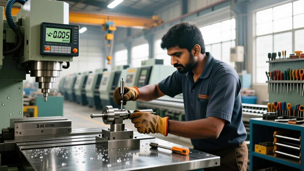
Even if the machine arrives perfectly calibrated from the OEM, transit over Indian road networks often knocks the column out of square. Before running the first production part, operators must perform a manual tramming verification.
Operator Standard: Per ISO 230-2:2014 Test Code for Machine Tools, the geometric accuracy of the spindle axis must be verified under static conditions. Relying solely on the machine's internal laser calibration data without physical dial-indicator verification is a critical setup error.
Step-by-Step Tramming Procedure
- Tooling: Mount a 250mm test bar in the spindle and attach a 0.001mm resolution dial indicator.
- Y-Axis Sweep: Position the indicator at the front edge of the table. Zero the dial. Move the Y-axis 300mm toward the column. The acceptable tolerance for a standard VMC is ±0.01mm over 300mm. If the indicator reads +0.03mm, the spindle is nodding backward; shim the rear foundation pads accordingly.
- X-Axis Sweep: Sweep across the X-axis (left to right) over a 500mm travel. Tolerance remains ±0.01mm. Deviations here indicate table twist, requiring diagonal leveling pad adjustments.
Tooling and Workholding for High-Mix Production
Indian job shops typically run high-mix, low-to-medium volume batches. Quick changeovers are vital to maintaining spindle uptime. The standard BT40 taper offers the optimal balance of rigidity for roughing steel and accessibility for deep cavity milling.
Workholding Investment: Avoid unbranded, locally cast vises for precision work. Invest in high-clamping-force mechanical vises like the Kurt DX6 or equivalent Indian-manufactured precision vises (e.g., Santosh or Vertex) that guarantee repeatability within 0.015mm. Always use a torque wrench on the vise handle to ensure consistent clamping pressure and prevent part distortion during finishing passes.For tool retention, ensure the drawbar pull force is tested quarterly. A BT40 spindle should maintain a minimum of 1,800 lbs (8 kN) of pull force. Degradation in Belleville washer stacks leads to tool pullout during heavy roughing cycles, a common failure mode in shops neglecting preventative maintenance.
Preventative Maintenance in Tropical Climates
India's monsoon season introduces severe humidity, accelerating way-cover corrosion and degrading coolant integrity. A proactive maintenance matrix is non-negotiable.
| Frequency | Component | Actionable Protocol |
|---|---|---|
| Daily | Coolant System | Check concentration with a refractometer. Maintain 6-8% for semi-synthetic fluids (e.g., TRIM MicroSol). Top up with treated water, never raw tap water, to prevent calcium buildup. |
| Weekly | Way Lube System | Verify ISO VG 68 way oil flow at all metering units. Clear blocked lines immediately to prevent linear guide scoring. |
| Monthly | Spindle Taper | Clean the internal taper with a specialized lint-free cloth and isopropyl alcohol. Inspect for fretting corrosion caused by micro-movements of dull tool holders. |
| Quarterly | Cabinet Filters | Replace electrical cabinet intake filters. Clogged filters cause VFD (Variable Frequency Drive) overheating and thermal shutdowns during peak summer months (April-June). |
Troubleshooting Common 3-Axis Setup Failures
Symptom: Severe Chatter During Roughing
Cause: Often misdiagnosed as a tooling issue, chatter on a newly installed 3-axis VMC in India is frequently caused by inadequate floor rigidity or harmonic resonance from neighboring heavy machinery.
Fix: Perform a tap test on the machine base. If the foundation is transmitting vibration, install active or passive vibration isolation pads (e.g., Mason Industries) under the leveling feet. Additionally, reduce the radial width of cut (ae) to 50% of the tool diameter while maintaining high axial depth (ap) to shift the cutting frequency away from the machine's natural harmonic node.
Symptom: Dimensional Drift Along the Z-Axis
Cause: Thermal growth of the spindle housing or ballscrew. In non-climate-controlled Indian factories, ambient temperatures can reach 42°C, causing the Z-axis ballscrew to expand.
Fix: Implement a thermal warm-up cycle in the CNC control. Run a standardized 15-minute spindle and axis warm-up program at the start of every shift. If the machine lacks a ballscrew cooling system, program Z-axis tool offsets to compensate for predictable thermal growth (typically +0.02mm to +0.05mm over a 4-hour continuous cycle).
Symptom: Servo Alarms During Rapid Traverses
Cause: Voltage sag during simultaneous 3-axis rapid movements (G00), pulling the DC bus voltage below the drive's minimum threshold.
Fix: Check the input voltage at the machine's main disconnect switch during a 3-axis rapid move. If the voltage drops below 380V, upgrade the facility's step-down transformer or reduce the rapid override to 50% to lower the instantaneous current draw until the electrical infrastructure is upgraded.