Smart Electrical Setups for M Code CNC Machine Optimization
Discover how modern electrical architectures, VFDs, and IoT monitoring optimize m code cnc machine execution, reducing power spikes and improving reliability.
The Electrical Anatomy of M-Code Execution
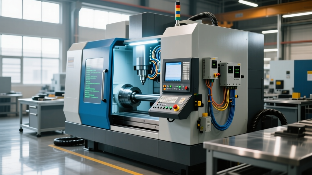
While G-codes dictate the geometric path of a cutting tool, M-codes (miscellaneous codes) are the discrete electrical triggers that manage the physical auxiliary systems of a CNC machine. When a controller processes an M08 (coolant on) or M06 (tool change) command, it does not move an axis; instead, it routes a 24VDC logic signal through a programmable logic controller (PLC) to close high-voltage contactors, fire pneumatic solenoids, or ramp up variable frequency drives (VFDs). In 2026, the efficiency and reliability of an m code cnc machine are entirely dependent on the sophistication of its electrical power setup and control cabinet architecture.
Legacy machines often rely on hard-wired, across-the-line starters and basic electromechanical relays to execute M-codes. This results in massive inrush current spikes, premature contactor pitting, and inefficient power consumption. Modern manufacturing facilities are now retrofitting and spec'ing new CNC electrical cabinets with solid-state relays, regenerative drives, and edge-computed IoT power monitoring to ensure that every M-code fires with millisecond precision and minimal energy waste.
Technical Callout: The Voltage Tier SystemA standard 2026 CNC electrical cabinet divides power into three distinct tiers to isolate noise and protect logic circuits:
1. 480V/240V 3-Phase AC: Main spindle drives, heavy coolant pumps, and hydraulic power units.
2. 120V AC: Control transformers, cabinet cooling fans, and operator panel displays.
3. 24V DC: PLC logic, M-code relay coils, I/O modules, and pneumatic solenoid valves.
Upgrading Auxiliary Systems for High-Frequency M-Codes
The most频繁 (frequent) M-codes in a standard milling cycle—M03/M04 (spindle start), M08/M09 (coolant on/off), and M06 (tool change)—place the highest cyclic stress on electrical components. Optimizing these specific circuits is where modern electrical engineering yields the highest return on investment.
Spindle Drive and Regenerative VFDs (M03 / M04)
Executing an M03 command on a 20-horsepower spindle motor traditionally required a direct-on-line (DOL) starter or a basic VFD, pulling up to 600% of the full-load amperage during startup. Modern 2026 setups utilize active front-end (AFE) regenerative VFDs. When an M05 (spindle stop) or M04 (reverse) is commanded, the kinetic energy of the heavy spindle rotor is converted back into electrical energy and fed back into the facility's grid, rather than being burned off as heat in a braking resistor. According to the U.S. Department of Energy Advanced Manufacturing Office, integrating regenerative drives in high-cycle CNC environments can reduce spindle-related energy consumption by up to 32%.
Servo-Driven Coolant Pumps (M08 / M09)
Standard M08 execution triggers a 3-phase AC induction coolant pump that runs at a fixed RPM, relying on manual valves to adjust pressure. Advanced electrical setups replace these with 240V 3-phase servo-driven pump motors. The PLC modulates the servo drive based on real-time pressure transducer feedback. This eliminates the inrush current spike every time M08 is called and reduces continuous power draw by matching pump output exactly to the tool's coolant requirements.
| M-Code Function | Legacy Electrical Component | 2026 Smart Upgrade | Primary Benefit |
|---|---|---|---|
| M03/M04 (Spindle) | Standard VFD + Braking Resistor | Regenerative AFE Drive | Grid feedback, zero heat waste |
| M08 (Coolant) | DOL Contactor + AC Induction Motor | Servo-Drive Pump + IoT Flow Sensor | Variable flow, 40% energy drop |
| M06 (Tool Change) | 120V AC Pneumatic Solenoids | 24V DC Proportional Valves | Faster shift, lower coil heat |
| M19 (Spindle Orient) | Mechanical Pin / Encoder | Closed-Loop Servo Spindle Motor | Instant orientation, no wear |
IoT Edge Computing and M-Code Power Profiling
The most significant innovation in CNC electrical setups is the integration of IoT edge power meters, such as the Schneider Electric PowerLogic PM5560 series, directly into the main control cabinet. These devices sample voltage and current waveforms at 128 samples per cycle. By synchronizing the power meter's data logs with the CNC controller's M-code execution log via MTConnect or OPC-UA, maintenance teams can perform 'power profiling' on specific M-codes.
For example, if an M06 tool change command normally draws a 4-amp spike for 0.8 seconds to fire the carousel pneumatic cylinder, but the IoT meter begins recording a 6-amp spike lasting 1.4 seconds, the system flags a predictive maintenance alert. This indicates mechanical binding in the tool changer or a degrading solenoid coil long before the machine faults out and crashes a tool. The NIST Smart Manufacturing Systems Test Bed has extensively documented how coupling machine logic states with high-frequency electrical telemetry reduces unplanned downtime by predicting electromechanical failures at the component level.
'Monitoring the electrical signature of discrete M-code executions transforms the CNC control cabinet from a passive power distribution box into an active diagnostic sensor array.'
— 2025 IEEE Transactions on Industrial Informatics, Smart Grid Integration in Machine Tools
Step-by-Step: Spec'ing a 2026-Compliant CNC Electrical Cabinet
Whether ordering a new machining center or retrofitting an existing control panel, ensuring the electrical setup complies with modern efficiency and safety standards requires strict adherence to component selection and wiring protocols. The NFPA 79 (Electrical Standard for Industrial Machinery) dictates rigorous guidelines for these environments.
- Isolate VFD Cabling: When wiring the spindle drive for M03/M04 execution, use XHHW-2 shielded VFD cable. Ground the shield at both the drive and the motor peckerhead to prevent high-frequency common-mode noise from inducing phantom voltages in the 24VDC M-code logic circuits.
- Implement Solid-State Relays (SSRs): Replace electromechanical contactors for high-cycle M-codes (like M08 coolant or M21/M22 chuck open/close) with DIN-mounted SSRs. SSRs have no moving parts, eliminating contact arcing and bouncing, ensuring the PLC receives exact execution timing.
- Deploy Distributed I/O Blocks: Instead of running dozens of individual 24VDC wires from the main cabinet to the machine's tool changer and coolant manifolds, use IP67-rated distributed I/O blocks connected via a single EtherCAT or PROFINET cable. This drastically reduces cabinet clutter and voltage drop over long cable runs.
- Install 24VDC Redundant Power Supplies: The 24VDC logic tier is the brain of M-code execution. Use dual 20-amp 24VDC power supplies in a redundant configuration with a diode decoupling module. If one supply fails during an M06 tool change, the secondary instantly carries the load without dropping the PLC logic, preventing a mid-cycle crash.
- Integrate Smart Circuit Breakers: Replace standard thermal-magnetic breakers on auxiliary 120V circuits (chip conveyors, coolant skimmers) with electronic smart breakers that allow remote resetting and provide precise amperage telemetry to the facility's SCADA system.
Troubleshooting Matrix: Electrical Faults in M-Code Execution
When an m code cnc machine fails to execute a command, the issue is rarely in the G-code program itself; it is almost always a failure in the electrical translation layer. Use this diagnostic matrix to isolate faults rapidly.
Symptom: M08 (Coolant) Command Ignores or Delays
- Electrical Cause 1: 24VDC logic voltage drop across a corroded terminal block, failing to meet the 18VDC minimum pull-in voltage of the contactor coil.
- Electrical Cause 2: The coolant pump's thermal overload relay has tripped due to phase imbalance or clogged impeller strain, breaking the 24VDC feedback loop to the PLC.
- Actionable Fix: Measure voltage directly at the contactor coil terminals while the M08 is active. If below 20VDC, trace back to the PLC output card. Reset the thermal overload and check 3-phase amperage on the pump motor with a clamp meter (should be within 5% across all three legs).
Symptom: M06 (Tool Change) Halts Mid-Rotation
- Electrical Cause: The 24VDC proximity switch confirming the carousel's 'home' position is misaligned or failing to trigger, causing the PLC to halt the sequence to prevent a crash.
- Actionable Fix: Put the machine in manual jog mode. Manually rotate the carousel and monitor the PLC I/O diagnostic screen. If the input bit does not illuminate when the metal flag passes the sensor, adjust the sensor gap to exactly 1.5mm (for standard inductive PNP sensors) and verify the 24VDC supply to the sensor's brown wire.
Symptom: Spindle Fails to Orient (M19)
- Electrical Cause: Encoder signal degradation. The high-frequency pulses from the spindle encoder are being corrupted by electromagnetic interference (EMI) from an unshielded adjacent power cable.
- Actionable Fix: Inspect the encoder cable routing. Ensure it is separated from 480V VFD cables by at least 12 inches, or divided by a grounded metal barrier. Replace the encoder cable with a high-flex, double-shielded twisted-pair cable, ensuring the drain wire is terminated correctly at the drive ground lug.