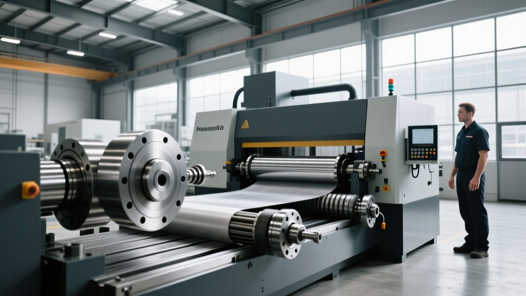
Optimizing Your CAD Drawing for CNC Machine Power Setup
Learn how to leverage a CAD drawing for CNC machine electrical setups, covering 2026 power trends, 3-phase requirements, and regenerative drive tech.
The Shift to Digital Twin Electrical Planning
Modern manufacturing facilities no longer rely on static paper schematics to plan shop floor power distribution. In 2026, facility engineers import the CAD drawing for CNC machine electrical layouts directly into Building Information Modeling (BIM) software to simulate load flow, voltage drop, and harmonic distortion before a single trench is dug. This digital twin approach prevents the catastrophic breaker trips and drive failures that historically plagued shops scaling up their machining capabilities.
Translating a precise CAD drawing for CNC machine power distribution requires understanding the intersection of heavy inductive loads, regenerative braking systems, and strict industrial compliance codes. Below is the definitive framework for decoding your machine's electrical schematics and executing a flawless power drop installation.
⚠️ NFPA 79 Compliance Alert: According to the NFPA 79 Electrical Standard for Industrial Machinery, every CNC power drop must feature a lockable, externally operable main disconnect switch rated for the full load amperage (FLA) of the machine. Failing to isolate the control circuit from the main power feed violates OSHA lockout/tagout (LOTO) mandates.Core Power Specifications: Decoding the Schematics
The electrical cabinet schematic within your machine's CAD documentation will list the Full Load Amps (FLA) and peak kVA requirements. Sizing your wire and overcurrent protection based solely on the spindle motor's horsepower is a critical error; you must account for the simultaneous operation of the spindle, axis servos, coolant pumps, and chip conveyors.
| Machine Model | Voltage / Phase | FLA (Amps) | Wire Size (THHN) | Breaker / Fuse |
|---|---|---|---|---|
| Haas VF-2SS | 230V / 3-Phase | 40A | #4 AWG | 60A Class RK1 |
| Mazak INTEGREX i-200S | 400V / 3-Phase | 63A | #2 AWG | 80A MCCB |
| DMG MORI NLX 2500 | 480V / 3-Phase | 50A | #3 AWG | 70A MCCB |
Managing Phase Conversion and Voltage Stability
Many job shops operate in light industrial zones lacking native 480V or 230V 3-phase utility power. When your CAD drawing for CNC machine electrical requirements specifies 3-phase input, you must bridge the gap using phase conversion technology. The choice between a Rotary Phase Converter (RPC) and a Solid-State Variable Frequency Drive (VFD) converter drastically impacts machine longevity.
Rotary Phase Converters (RPC)
An RPC uses an idler motor to generate a synthetic third leg of power. For a 20HP CNC mill requiring 230V, expect to invest between $3,500 and $4,500 in a premium CNC-rated RPC (such as those from Phase-A-Perfect or AmeriPhase). Critical spec: The voltage imbalance between the three legs must not exceed 3%, or the CNC's internal power supply will trigger low-voltage alarms and halt production.
VFD-Driven Phase Conversion
For smaller lathes and mills under 10HP, a VFD can accept 220V single-phase input and output 220V 3-phase. However, VFDs output a Pulse Width Modulated (PWM) sine wave. If your machine's CAD schematic indicates sensitive Fanuc or Siemens servo drives, the high-frequency harmonics from a standard VFD can degrade motor insulation over time. Always install a dV/dT filter or sine wave filter between the VFD and the machine's main disconnect.
2026 Innovations: Regenerative Drives and Active Front Ends
The most significant shift in CNC power architecture is the widespread adoption of Active Front End (AFE) regenerative drives. When a heavy spindle decelerates from 12,000 RPM to zero during a tool change, the kinetic energy is converted back into electrical energy.
"In older CNC architectures, this regenerative energy was burned off as heat through massive braking resistor banks. Modern AFE drives push this power cleanly back into the facility's grid, reducing overall shop power consumption by up to 18% and eliminating the need for dedicated HVAC cooling on the electrical cabinets." — Industrial Power Quality Report, 2025
When reviewing the CAD drawing for CNC machine layouts featuring AFE technology (common in high-end 5-axis machines like the Hermle C42), ensure your facility's main transformer is equipped to handle bidirectional power flow. Standard utility meters may spin backward or throw fault codes if not programmed for net-metering.
Step-by-Step Power Drop Installation Framework
Execute the physical power drop using this field-tested sequence to ensure compliance with OSHA 1910.303 electrical safety standards and optimal machine performance.
- Conduit Routing and Sizing: Run rigid galvanized steel or heavy-wall EMT conduit. For a 60A drop using #4 AWG THHN wire, use a minimum 1-inch conduit to allow for heat dissipation and future upgrades. Maintain a 12-inch separation from low-voltage Ethernet and encoder cables to prevent electromagnetic interference (EMI).
- Disconnect Installation: Mount a NEMA 12 (indoor, dust-tight) fused disconnect switch within 6 feet of the machine. Use dual-element, time-delay Class RK1 fuses. These fuses tolerate the brief inrush current (often 600% of FLA for milliseconds) when the CNC's main contactor engages, without nuisance tripping.
- Grounding Electrode System: Do not rely solely on the conduit for grounding. Pull a dedicated #6 AWG bare copper grounding wire alongside your phase conductors. Bond this wire to the machine's main grounding busbar and the facility's grounding electrode system. A poor ground reference will cause erratic servo behavior and data corruption in the CNC controller.
- Phase Rotation Verification: Before terminating the wires at the machine's main breaker, use a phase rotation meter. If L1-L2-L3 is reversed, the machine's coolant pump will run backward, starving the spindle of lubrication and causing catastrophic bearing failure within minutes.
Troubleshooting Power Quality Issues
Even with a perfect installation, grid anomalies occur. Use this diagnostic matrix to resolve common electrical faults.
Symptom: Random Servo Alarms and Controller Reboots
- Cause: Voltage sags caused by heavy equipment (like overhead cranes or large air compressors) starting on the same bus.
- Fix: Install a Constant Voltage Transformer (CVT) or an industrial Uninterruptible Power Supply (UPS) specifically sized for the CNC's 24V DC control circuit and servo drives. A 3kVA industrial UPS typically costs around $1,800 and prevents thousands of dollars in scrapped parts.
Symptom: Overheating Electrical Cabinet Components
- Cause: High Total Harmonic Distortion (THD) from neighboring VFDs or laser cutters polluting the sine wave.
- Fix: Deploy an active harmonic filter at the main distribution panel. Modern active filters inject opposing currents to cancel out harmonics, keeping THD below the 5% threshold recommended by IEEE 519 standards.
By treating the CAD drawing for CNC machine electrical schematics as a dynamic data source rather than a static PDF, facility managers can future-proof their power infrastructure, ensuring maximum uptime and protecting multi-million-dollar machining assets from preventable electrical failures.