CNC Wheel Machining: Aluminum Maintenance Schedules
Optimize CNC wheel machining operations with strict aluminum maintenance schedules. Prevent spindle wear and chip buildup with expert protocols.
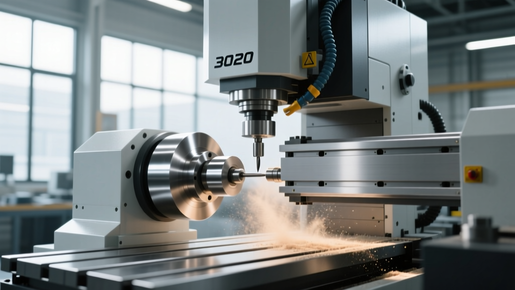
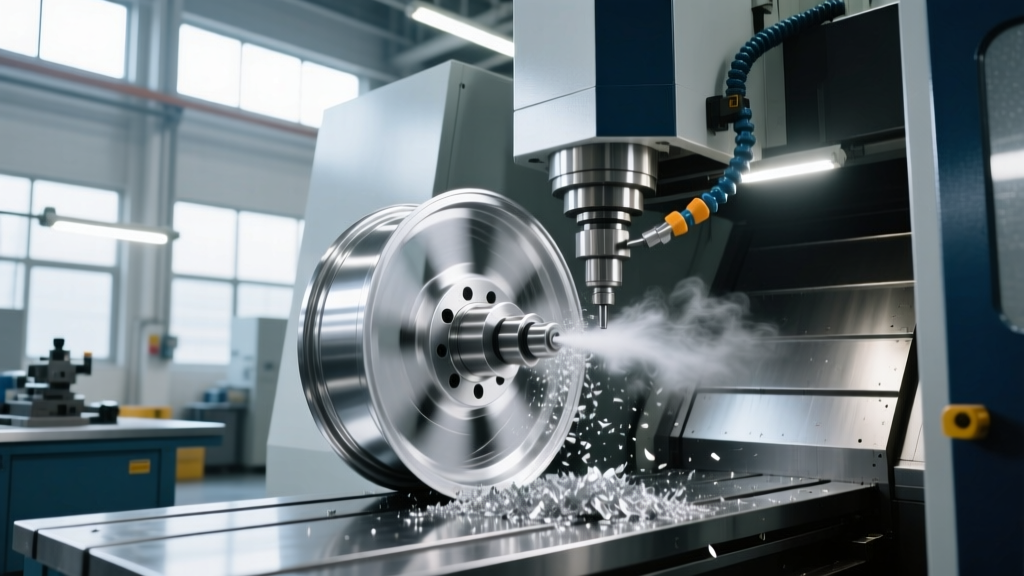
Cast aluminum alloy wheels, predominantly manufactured from A356-T6 alloy, dominate both OEM and aftermarket automotive sectors. Machining these wheels on dedicated horizontal machining centers (HMCs) or 5-axis CNC trunnion tables exposes the equipment to extreme abrasive wear, massive chip volumes, and aggressive coolant washdowns. Standard steel-cutting maintenance intervals are entirely inadequate for CNC wheel machining in aluminum. The high silicon content in the workpiece material accelerates component degradation, demanding a specialized, high-frequency preventative maintenance (PM) framework to protect machine geometry and spindle integrity.
⚠️ CRITICAL METALLURGICAL FACTOR: A356-T6 cast aluminum contains approximately 7% silicon. During high-speed face milling and spoke pocketing, this silicon acts as a microscopic abrasive. If fine aluminum-silicon dust breaches the way covers or spindle labyrinth seals, it forms a lapping compound with way oil, destroying linear guides and ball screws in a fraction of their rated lifespan.Daily Shift Maintenance: Coolant Chemistry and Chip Evacuation
Aluminum wheel machining generates a mix of stringy chips from rim profiling and fine, powdery swarf from face milling. This combination is notorious for jamming chip conveyors and degrading coolant. According to Modern Machine Shop guidelines on aluminum machining, managing the chemical reaction between aluminum fines and water-based coolants is the first line of defense for machine preservation.
Coolant Concentration and pH Verification
Aluminum fines react with water to produce hydrogen gas and aluminum hydroxide, which rapidly depletes coolant additives and drops the pH level. A drop below pH 8.5 causes aluminum staining and accelerates machine tool corrosion.
- Refractometer Calibration: Check coolant concentration at the start of every shift. For synthetic or semi-synthetic coolants used in wheel machining, apply the manufacturer's refractometer correction factor (typically 1.5 to 2.0). Target a strict 6% to 8% concentration.
- pH Testing: Maintain a pH between 8.8 and 9.2. If pH drops, add a specialized alkaline reserve booster rather than dumping and replacing the sump, which disrupts the biostatic balance.
- Tramp Oil Skimming: Run centrifugal tramp oil separators continuously. Tramp oil emulsifies with aluminum fines to create a thick, abrasive sludge that clogs 50-micron drum filters.
Chip Auger and Conveyor Torque Checks
Wheel machining operations produce upwards of 150 kg of chips per hour on high-volume lines. Operators must verify that the chip conveyor torque limiter is set correctly (usually between 15-25 Nm depending on the conveyor manufacturer). A slipping torque limiter indicates a mechanical jam in the auger trough, often caused by long, stringy rim chips wrapping around the drive shaft. Clearing these jams daily prevents motor burnout and belt snapping.
Weekly Service Protocols: Way Covers and Spindle Purge
The transition from daily operator checks to weekly technician service focuses on sealing the machine's critical kinematic components against silicon-aluminum dust ingress.
Way Cover Wiper Inspection and Replacement
Standard polyurethane wipers degrade quickly when exposed to sharp aluminum chips. Maintenance technicians must inspect the way cover wipers on all linear axes weekly. If any aluminum dust is visible on the linear guide rails behind the wiper, immediate replacement is required. Upgrade to specialized aluminum-repellent wipers with integrated brass scraper blades, which prevent the soft aluminum chips from embedding into the wiper lip and scoring the rail.
Spindle Labyrinth Air Purge Verification
High-frequency spindles (15,000 to 24,000 RPM) used for wheel finishing rely on positive air pressure to keep contaminants out of the bearing housing.
- Disconnect the air purge line at the spindle manifold.
- Attach a calibrated inline pressure gauge.
- Verify the static pressure reads between 15 PSI and 25 PSI (refer to specific OEM specs, such as those found in the Haas Automation service documentation).
- Check the inline 5-micron desiccant filter for moisture and aluminum dust. A saturated desiccant filter drops the purge pressure and allows humid, contaminated air into the labyrinth seal.
Preventative Maintenance Matrix for Aluminum Wheel CNCs
| Maintenance Task | Frequency | Target Specification / Tolerance | Estimated Cost of Failure |
|---|---|---|---|
| Coolant Concentration & pH Check | Daily (Per Shift) | 6-8% Conc. / 8.8-9.2 pH | $3,000 (Sump dump & machine washdown) |
| Chip Conveyor Torque Limiter Check | Daily | 15-25 Nm (No slip under load) | $1,200 (Drive motor & belt replacement) |
| Way Cover Wiper Inspection | Weekly | Zero visible dust on linear rails | $8,500 (Linear guide block & rail scoring) |
| Spindle Labyrinth Air Purge Test | Weekly | 15-25 PSI positive pressure | $35,000+ (Catastrophic spindle bearing failure) |
| ATC Arm Cam Box Grease & Pocket Check | Monthly | Retention force > 2000 lbs | $6,000 (ATC arm crash & spindle taper damage) |
| Axis Circularity Ballbar Test | Quarterly | Less than 0.008mm deviation | Scrapped wheel batches (Hub bore out-of-tolerance) |
Monthly and Quarterly Deep Service: ATC and Axis Geometry
As detailed by Sandvik Coromant's material knowledge base on aluminum, non-ferrous machining often requires specialized, high-rake tooling that can be physically large and heavy. CNC wheel machining utilizes massive custom form tools, such as PCD-tipped rim cutters and large diameter face mills, which place severe mechanical stress on the Automatic Tool Changer (ATC).
ATC Arm Calibration for Heavy Wheel Fixtures
Standard ATC arms are typically rated for tools weighing up to 12 kg. Wheel machining tools frequently exceed 18 kg. This over-spec weight accelerates wear on the ATC cam box and pocket retention clips.
- Cam Box Lubrication: Purge and repack the ATC cam box with high-tack lithium-complex grease monthly. Standard way oil will leak out of the cam box seals under the high inertial loads of swinging a 20 kg tool.
- Pocket Retention Force: Use a calibrated pull-force gauge to test the tool retention clips in the magazine. They must hold a minimum of 2000 lbs of pull force. If a heavy wheel cutter slips during the tool change cycle, it will crash into the spindle taper, causing $5,000+ in immediate damage and weeks of downtime.
Quarterly Ballbar Testing for Hub Bore Tolerances
The center hub bore of an aluminum wheel requires strict circularity tolerances (often within 0.02mm) to prevent vehicle vibration. Quarterly Renishaw ballbar testing is mandatory to detect servo mismatch and backlash in the X and Y axes before they manifest as out-of-tolerance bores. If the ballbar plot shows a 45-degree diagonal ovality, the axis gibs require adjustment or the ball screw thrust bearings are wearing from the heavy axial loads of face milling.
"When machining high-silicon aluminum alloys, the machine tool is effectively processing a mild abrasive. The facilities that achieve 95%+ spindle uptime on wheel lines are the ones that treat way cover integrity and coolant filtration with the same rigor as spindle runout."
— Senior Applications Engineer, Automotive Powertrain & Chassis Division
Annual Overhaul: Spindle Runout and Ball Screw Backlash
After 4,000 to 6,000 hours of continuous aluminum wheel machining, the cumulative effect of thermal cycling and abrasive exposure necessitates a comprehensive annual overhaul.
Spindle Taper Runout and Drawbar Force
Aluminum chips are easily blown into the spindle taper during tool changes, even with standard air blasts. Over time, microscopic chip embedding causes taper fretting. Annually, technicians must clean the taper with a specialized resin-bonded cleaning stick (never use abrasive Scotch-Brite pads, which alter the taper geometry). Measure toolholder pull-stud retention force using a digital drawbar force gauge; it must exceed the OEM specification (typically 2,500 to 3,500 lbs for HSK-A63 or CAT40 interfaces) to prevent tool chatter during heavy roughing passes.
Laser Interferometry for Ball Screw Compensation
Perform full-travel laser interferometry on all linear axes to map and compensate for ball screw backlash and pitch error. In aluminum wheel machining, the X and Y axes experience high dynamic reversal loads during spoke pocketing. Update the CNC controller's backlash compensation parameters to ensure positioning accuracy remains below 0.005mm across the entire working envelope, ensuring the wheel mounting pad surfaces remain perfectly coplanar.