Troubleshooting Your Homemade CNC Machine for Composite Cutting
Fix delamination, tool wear, and chatter on your homemade CNC machine when cutting carbon fiber, G10, and fiberglass composites. Expert repair guide.
The Reality of Cutting Composites on Homemade CNC Routers
Building a homemade CNC machine—whether it is a PrintNC, an MPCNC, or an OpenBuilds LEAD system—is a massive achievement. However, transitioning from cutting softwoods and acrylics to advanced composite materials like carbon fiber, fiberglass, G10, and Kevlar introduces severe mechanical and thermal challenges. Composites are highly abrasive, prone to delamination, and generate hazardous particulate that can destroy unprotected linear motion systems and short out stepper drivers.
Industrial CNC routers utilize 10,000-pound cast-iron frames, 15HP spindles, and sealed linear guideways to manage these forces. When you attempt to machine composites on a DIY aluminum extrusion or steel-tube frame, you must compensate for lower rigidity and torque through precise software tuning, specialized tooling, and aggressive dust mitigation. This guide provides exact troubleshooting parameters to optimize your homemade CNC machine for composite material cutting.
⚠️ SAFETY WARNING: Respiratory and Electrical HazardsCarbon fiber and fiberglass dust are severe respiratory hazards. According to NIOSH guidelines on composite materials, airborne synthetic fibers can cause irreversible lung damage. Furthermore, carbon fiber dust is highly conductive and will short-circuit exposed electronics. Never cut composites without a fully enclosed positive-pressure hood and a HEPA-filtered extraction system.
Diagnosing Delamination and Tear-Out in Layered Composites
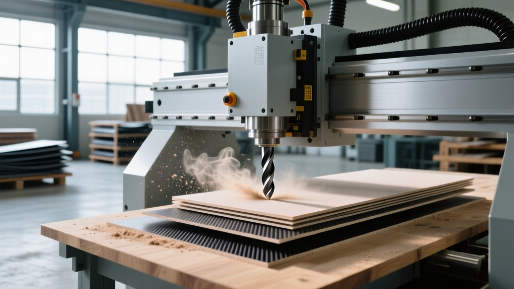
Delamination occurs when the cutting forces exceed the shear strength of the epoxy or resin matrix binding the composite layers. On a homemade CNC, Z-axis flex and improper tool geometry are the primary culprits. If your top or bottom layers are fraying, evaluate your tooling against the matrix below.
| Tool Type | Shear Geometry | Best Application | Homemade CNC Suitability |
|---|---|---|---|
| Straight Flute | 0° (Neutral) | Engraving, light scoring | Poor (Causes severe top/bottom tear-out) |
| Upcut Spiral | Right-Hand | Pocketing, chip evacuation | Fair (Leaves clean bottom, frays top layer) |
| Downcut Spiral | Left-Hand | Top-surface finishing | Good (Pushes material down, but packs chips in slots) |
| Compression Cutter | Mixed (Upcut base, Downcut top) | Through-cutting, profiling | Excellent (Requires rigid Z-axis and precise DOC) |
The Compression Bit Depth-of-Cut (DOC) Trap
A common mistake on DIY machines is using a 1/4-inch compression bit (such as the Onsrud 63-714 series) but failing to set the Depth of Cut (DOC) correctly. Compression bits feature an upcut spiral at the tip and a downcut spiral near the shank. The transition point (the shear line) must be positioned exactly at the mid-plane of your material. If your Z-axis suffers from 0.010-inch backlash, the shear line will pull the top layer up and push the bottom layer down simultaneously, causing catastrophic delamination. Fix: Perform a Z-axis backlash compensation test using a dial indicator and adjust your GRBL/Mach3 backlash settings to under 0.002 inches before running compression toolpaths.
Stepper Motor Stalling and Chatter Under Abrasive Loads
Composites require high feed rates to prevent the friction heat from melting the resin matrix, which leads to tool clogging and recutting of hardened chips. However, pushing a NEMA 23 or NEMA 34 stepper motor to the required 150–250 Inches Per Minute (IPM) often results in mid-cut stalling or severe chatter on lightweight homemade frames.
💡 EXPERT TIP: NEMA Torque Curves and MicrosteppingStepper motors lose torque exponentially as RPM increases. Running your drivers at 1/16 or 1/32 microstepping smooths the motion but drastically reduces holding torque at high speeds. If your machine chatters when profiling carbon fiber, switch your TMC2209 or DRV8825 drivers to 1/4 or 1/8 microstepping and increase the VREF current limit by 15% to regain high-speed torque.
Tuning GRBL Acceleration Parameters
If your homemade CNC uses GRBL v1.1 or FluidNC, the default acceleration settings are usually too aggressive for the lateral cutting forces generated by composites. When the tool engages the material, the sudden load causes the stepper to skip steps if the acceleration ramp is too steep.
- $110, $111 (Max Feed Rate): Set to 8000 mm/min (approx 315 IPM) to allow headroom, but program your CAM toolpaths to max out at 4000 mm/min (157 IPM) for 1/4-inch carbon fiber.
- $120, $121 (Acceleration): Reduce X and Y acceleration from the default 500 mm/s² down to 150 mm/s². This creates a longer, smoother ramp-up, preventing the inertial shock that causes skipped steps during directional changes in contouring operations.
- $130, $131 (Junction Deviation): Lower to 0.05 mm to force the controller to slow down more aggressively at sharp corners, preserving edge quality on fiberglass parts.
Linear Motion Degradation from Composite Micro-Dust
The dust generated by machining G10 or carbon fiber is essentially microscopic glass and sharp carbon shards. If your homemade CNC relies on V-slot wheels (POM or Delrin) riding on aluminum extrusions, this dust will embed into the wheels, turning them into grinding stones that rapidly destroy the V-slot tracks.
Upgrading and Sealing Linear Motion
To troubleshoot premature linear motion failure, you must transition from open V-slot wheels to sealed linear guideways. Profile linear rails (such as HGR15 or HGR20) with sealed carriage blocks are mandatory for composite cutting. However, even sealed rails will fail if the dust breaches the wiper seals.
- Install Bellows Covers: Fabricate or purchase accordion-style bellows to cover the X and Y linear rails completely. This physical barrier prevents dust accumulation on the rail shafts.
- Positive Pressure Enclosures: Build an acrylic enclosure around your linear motion components and route a low-CFM filtered air line inside. The positive air pressure will force dust out of the carriage seals rather than allowing it to be sucked in during rapid movements.
- Lead Screw Protection: Replace open lead screws with ball screws equipped with integrated wiper seals, or enclose ACME lead screws in PTFE tubing with a drag-chain cable carrier system.
Spindle Runout and Tool Life Optimization
Many DIY CNC builders utilize inexpensive 1.5kW or 2.2kW Chinese water-cooled spindles. While powerful, these spindles often suffer from 0.002-inch to 0.004-inch runout at the collet nut. According to Harvey Tool's composite machining guidelines, excessive runout causes uneven load distribution on the flutes of solid carbide bits, leading to immediate micro-chipping and a 90% reduction in tool life.
Measuring and Correcting Spindle Runout
Mount a dial indicator with 0.0001-inch resolution against the shank of a premium carbide blank. Rotate the spindle by hand. If runout exceeds 0.0005 inches, you must troubleshoot the collet system:
- Clean the Taper: Use isopropyl alcohol and a lint-free swab to clean the internal ER11 or ER20 taper. Even a single carbon fiber particle trapped in the taper will push the collet off-center.
- Upgrade to Precision Collets: Discard the factory collets. Purchase ER20 'AA' grade precision collets (guaranteed <0.0002-inch TIR) from manufacturers like Techniks or Parlec.
- Check the Drawbar/Nut: Ensure the collet nut bearings are not seized. A seized bearing will cause the nut to twist the collet during tightening, inducing severe runout.
Electrical Shorts from Conductive Carbon Dust
Carbon fiber dust is electrically conductive. If it infiltrates your control box, it will bridge the gaps between the pins on your stepper motor drivers and microcontrollers, resulting in dead short circuits and fried mainboards.
"We see dozens of DIY CNC control boards destroyed every month because builders machine carbon fiber without sealing their electronics. Conformal coating and positive-pressure NEMA enclosures are not optional; they are mandatory for survival in a composite environment."
— Industrial Automation Technician Report, 2025
The Fix: Open your control enclosure and apply an acrylic or silicone conformal coating (such as MG Chemicals 419D) directly over the stepper drivers, Arduino/Raspberry Pi boards, and breakout boards. This creates a non-conductive dielectric barrier over the circuitry. Next, seal all cable entry glands with silicone and install a small 12V PC fan with a HEPA filter blowing into the enclosure to maintain positive pressure.
Quick-Reference Troubleshooting Flowchart
Use this rapid diagnostic list when your composite cuts fail:
- Symptom: Top edge is frayed, bottom edge is clean.
Cause: Using an upcut bit or compression bit shear line is too high.
Fix: Switch to downcut bit or lower Z-axis DOC by 0.020 inches. - Symptom: Melted resin sticking to the end mill.
Cause: Feed rate is too slow, causing friction heat.
Fix: Increase feed rate by 30% and apply a blast of compressed air (not liquid coolant) to clear chips. - Symptom: Dimensional inaccuracy and rounded corners.
Cause: Stepper stalling due to high acceleration and lateral cutting forces.
Fix: Reduce GRBL $120/$121 acceleration to 150 mm/s² and reduce cornering speeds in CAM. - Symptom: Bit shatters within the first 10 seconds of cutting.
Cause: Spindle runout exceeding 0.001 inches or excessive DOC for the shank diameter.
Fix: Clean ER collet taper, upgrade to precision collets, and limit DOC to 1x tool diameter for carbon fiber.
Optimizing a homemade CNC machine for composite materials requires shifting your mindset from 'removing material' to 'shearing a highly abrasive, layered matrix.' By addressing Z-axis backlash, tuning stepper acceleration, sealing your linear motion, and eliminating electrical dust hazards, your DIY build can produce aerospace-grade composite parts that rival industrial machinery.