Desktop CNC Machine Calibration: A Prototyping Buyer's Guide
Discover how desktop CNC machine calibration impacts rapid prototyping. Compare top benchtop mills, tolerances, and buying criteria for precision parts.
The Hidden Bottleneck in Desktop Prototyping
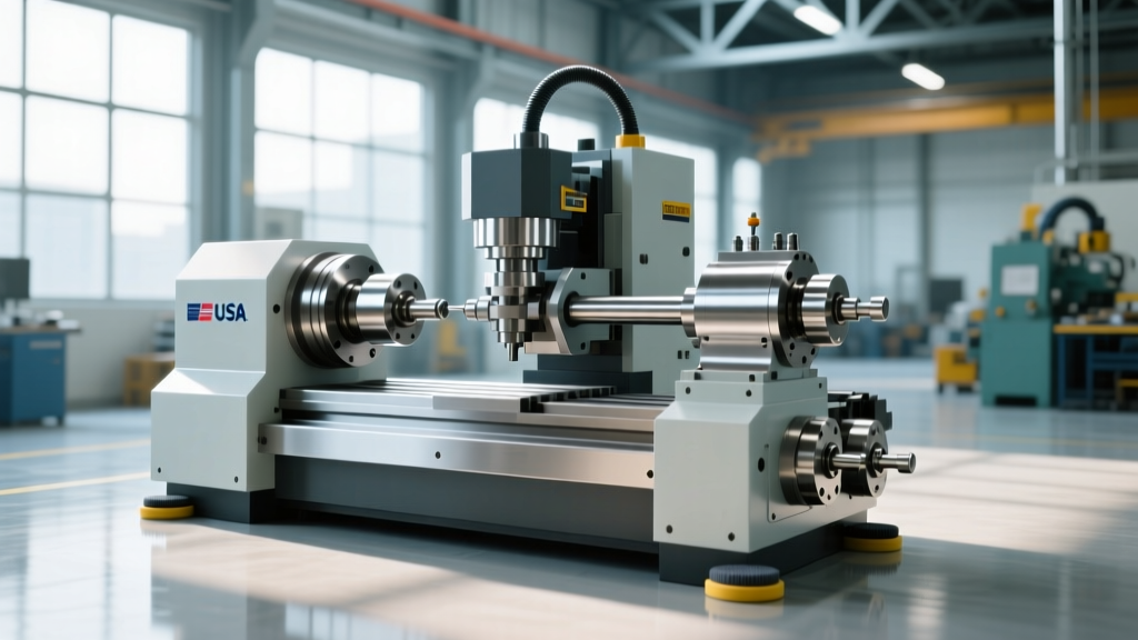
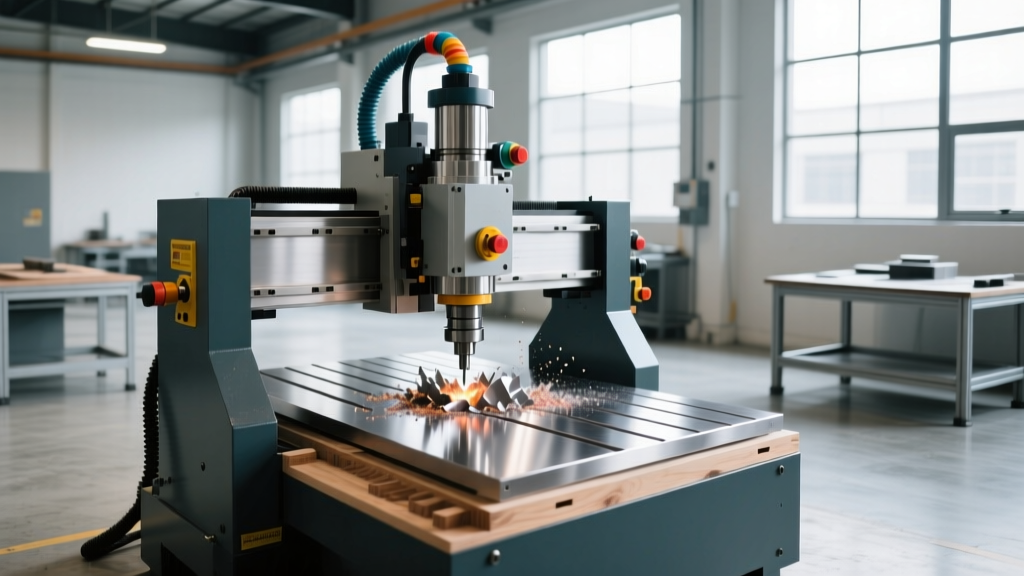
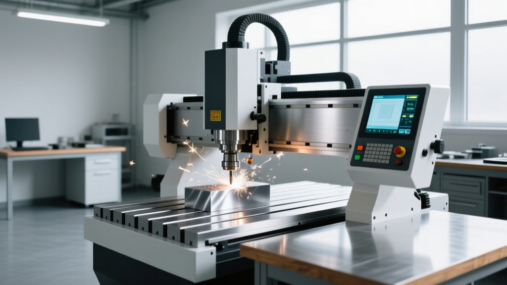
The transition from 3D printing to subtractive manufacturing on a benchtop scale promises tighter tolerances, superior surface finishes, and the ability to machine engineering-grade metals. However, the physical footprint of a desktop mill introduces unique mechanical challenges. Unlike a 3,000-lb cast-iron vertical machining center (VMC) that absorbs vibration and resists thermal growth, a 150-lb desktop mill operates on the edge of its structural rigidity. Consequently, desktop CNC machine calibration is not a one-time setup task; it is the defining factor between producing a functional aerospace prototype and a scrap bin full of out-of-tolerance parts.
When evaluating equipment for a rapid prototyping lab or engineering startup, buyers often fixate on spindle speed, travel distance, and software compatibility. Yet, according to data from the Society of Manufacturing Engineers (SME), the primary cause of scrapped micro-machined prototypes stems from uncorrected geometric errors and thermal drift—issues directly mitigated by rigorous calibration protocols. This guide dissects the calibration realities of the leading desktop CNC platforms and provides a framework for matching machine capability to your specific prototyping requirements.
The Physics of Benchtop Tolerances
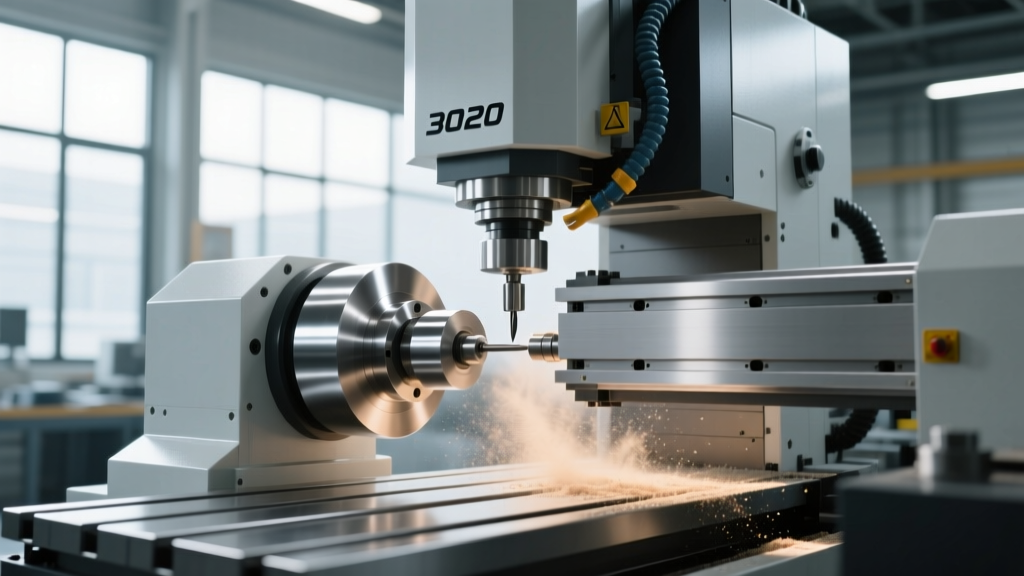
Small-format CNC machines rely on precision-ground ballscrews and linear guide rails, but the assembly and mounting of these components dictate real-world accuracy. Three mechanical phenomena require constant calibration attention on desktop units:
- Backlash and Pitch Error: Even with preloaded ballscrews, directional reversal introduces micro-movements. Without software backlash compensation calibrated to the specific wear state of the nuts, circular interpolation will result in ovality.
- Spindle Runout: A runout of just 0.0005 inches on a 1/8-inch end mill drastically alters the chip load per tooth, leading to premature tool breakage when machining hardened steels.
- Thermal Asymmetry: Desktop machines are frequently enclosed in acrylic or polycarbonate sound-dampening boxes. The trapped heat from the spindle motor and stepper drivers causes the Z-axis column to expand unevenly, shifting the tool tip relative to the workpiece by up to 0.002 inches over a 45-minute cycle.
2026 Desktop Mill Contenders: Calibration Profiles
The market for benchtop CNCs has matured, splitting into distinct tiers based on how the manufacturer approaches factory calibration and user-maintainable adjustments.
Tormach PCNC 440: The Heavyweight Benchtop
Retailing at approximately $5,500 for the base package, the Tormach PCNC 440 remains the benchmark for entry-level metal removal. It features a 3/4 HP spindle capable of 10,000 RPM and a rigid steel frame. Tormach utilizes the PathPilot controller, which includes built-in backlash compensation tools. However, the PCNC 440 requires manual tramming of the head and periodic verification of axis squareness using a precision 1-2-3 block and a 0.0005-inch resolution dial indicator. It is designed for users willing to perform hands-on mechanical calibration to achieve its rated ±0.0005-inch repeatability.
Bantam Tools PCNC 340: The Electronics & Soft Metal Specialist
Priced at $3,799, the Bantam Tools PCNC 340 is engineered specifically for high-speed milling of PCBs, Delrin, and 6061 aluminum. Bantam differentiates itself by integrating an automatic tool length probe directly into the machine bed, vastly simplifying Z-axis calibration and tool setup. The machine relies on high-precision NEMA 23 stepper motors rather than servos. While it lacks the raw torque of the Tormach for heavy steel cuts, its factory-calibrated kinematic chain is highly optimized for micro-tooling (down to 0.005-inch diameter end mills), provided the user maintains a clean, debris-free ballscrew environment.
Pocket NC V2-50: 5-Axis Kinematic Complexity
The Pocket NC V2-50 (starting around $5,200) brings simultaneous 5-axis machining to the desktop. With 5-axis setups, calibration complexity scales exponentially. A 0.001-inch error in the rotary trunnion table compounds into a massive tool-tip deviation at the outer edges of the work envelope. Pocket NC provides a Kinematic Calibration routine that requires the user to sweep a dial indicator against a precision calibration sphere mounted to the bed. This software-driven spatial error mapping is mandatory before running complex aerospace turbine blades or impeller prototypes.
Calibration Tolerances by Prototyping Material
Different materials demand varying levels of machine calibration strictness. The table below outlines the maximum allowable geometric errors based on the material being prototyped, aligning with guidelines often referenced in NIST advanced manufacturing research regarding micro-machining tolerances.
| Prototyping Material | Hardness (BHN) | Max Spindle Runout | Max Axis Backlash | Calibration Priority |
|---|---|---|---|---|
| FR-4 (PCB Substrate) | ~110 | ≤ 0.0010" | ≤ 0.0005" | Z-axis depth precision (prevents cutting through copper traces) |
| Delrin / POM | ~120 | ≤ 0.0008" | ≤ 0.0003" | Spindle tramming (prevents scalloping on flat surfaces) |
| 6061-T6 Aluminum | ~95 | ≤ 0.0005" | ≤ 0.0002" | Backlash compensation (critical for circular bore interpolation) |
| 17-4 PH Stainless | ~330 | ≤ 0.0002" | ≤ 0.0001" | Thermal drift mapping (prevents tool deflection and breakage) |
The 4-Step Benchtop Calibration Protocol
To extract VMC-level accuracy from a desktop footprint, engineering labs must implement a strict calibration cadence. The Association For Manufacturing Technology (AMT) emphasizes that predictive maintenance and regular geometric verification are essential for small-format machine longevity.
- Table Sweep and Head Tramming: Mount a 0.0005-inch dial test indicator in the spindle collet. Sweep a 12-inch arc across the machine bed. Adjust the tilt and nod bolts on the spindle head until the total indicator reading (TIR) is under 0.001 inches across the entire travel. Perform this monthly, or immediately after any heavy crash.
- Backlash Measurement and Compensation: Clamp a 1-2-3 block to the table. Position the dial indicator against the block. Command the machine to move the axis 0.100 inches in the positive direction, then 0.100 inches in the negative direction. The difference between the commanded move and the indicator reading is your backlash. Input this exact value into the machine controller's backlash compensation table.
- Spindle Runout Verification: Insert a precision ground 1/2-inch gauge pin into your highest-quality collet (ER11 or ER16). Measure the runout at the tip of the pin. If TIR exceeds 0.0004 inches, discard the collet. Desktop mills cannot afford the compounding error of worn tool holding.
- Thermal Drift Mapping: Mount an indicator on the bed pointing up at the spindle nose. Run the spindle at 8,000 RPM for 45 minutes with the enclosure closed. Record the Z-axis drop. Use this data to program a Z-axis wear offset in your CAM software that activates after the machine reaches thermal equilibrium.
Probe Integration: The ROI of Automated Calibration
Manual calibration using dial indicators is time-consuming and prone to human error. Integrating a touch probe transforms the calibration workflow. While a full Renishaw OMP60 optical probe system costs upwards of $6,000—exceeding the price of the desktop mill itself—alternatives exist. Bantam’s integrated tool length sensor automates Z-axis calibration, saving approximately 15 minutes per tool change. For Tormach users, the TTS (Tormach Tooling System) probe allows for semi-automated work coordinate system (WCS) setting. If your prototyping workflow involves machining multiple setups or flipping parts to machine the reverse side, investing in a probe system yields a return on investment within the first 50 parts by eliminating manual edge-finding errors.
Purchasing Decision Matrix: Which Desktop Mill Fits Your Lab?
Choose the Tormach PCNC 440 if: Your prototypes require machining steel, brass, or thick aluminum billets, and your team has the mechanical aptitude to perform manual tramming and ballscrew tensioning. It is the most robust platform for traditional subtractive prototyping.
Choose the Bantam Tools PCNC 340 if: Your primary output consists of custom PCBs, RF enclosures, microfluidic manifolds in Delrin, or wax masters for investment casting. The software ecosystem and automated Z-probing make it ideal for electrical and biomedical engineers who view the CNC as a utility rather than a hobby.
Choose the Pocket NC V2-50 if: You are prototyping complex aerospace geometries, turbine blades, or impellers that require undercuts and multi-sided machining in a single setup. Be prepared to dedicate significant time to kinematic calibration and 5-axis CAM toolpath verification.
Beyond the Machine: Environmental Factors
Desktop CNC machine calibration is ultimately futile if the environment undermines the machine's geometry. Benchtop mills are highly susceptible to ambient temperature fluctuations and floor vibrations. A prototyping lab located near a loading dock or an HVAC return vent will experience continuous Z-axis drift. Install the machine on a dedicated, vibration-dampened workbench—preferably a heavy maple butcher block top or a granite surface plate—and maintain the room temperature at a stable 68°F (20°C), the standard reference temperature for dimensional metrology. By treating the desktop CNC not as a toy, but as a precision metrology instrument that happens to cut metal, engineering teams can reliably hold tolerances that rival machines ten times their size and price.