How a CNC Machine Video Exposes Workholding Failures
Discover how analyzing a high-speed CNC machine video reveals hidden workholding deflection, fixture chatter, and clamping failures in real-world case studies.
The Blind Spot in Static Fixturing Design
Modern workholding engineering relies heavily on static Finite Element Analysis (FEA) to calculate clamping forces. However, static models fail to account for dynamic harmonic resonance, thermal expansion, and transient cutting forces. When aerospace and medical shops experience inexplicable chatter marks or out-of-tolerance dimensions, the culprit is rarely the toolpath; it is almost always dynamic fixture deflection. To bridge the gap between theoretical clamping force and actual part stability, advanced machine shops are turning to high-speed optical analysis. Reviewing a high-speed cnc machine video has become the ultimate diagnostic methodology for exposing micro-lift, jaw fretting, and harmonic workholding failures that static calculations completely miss.
According to Sandvik Coromant's machining knowledge base, forced vibration and self-excited chatter (regenerative chatter) are heavily influenced by the dynamic stiffness of the workholding system, not just the static clamping pressure. A standard 60 fps shop-floor camera cannot capture these phenomena. Chatter frequencies in end-milling typically range from 300 Hz to 800 Hz. To accurately diagnose fixturing failures, engineers must capture and analyze footage at frame rates exceeding 2,000 frames per second (fps).
Diagnostic Callout: The Aliasing Effect
When viewing a standard 30 fps or 60 fps cnc machine video of a spinning spindle or vibrating part, the motion often appears to slow down or move backward. This is the stroboscopic aliasing effect. Relying on standard security or smartphone footage to diagnose workholding chatter will lead to entirely incorrect conclusions about the frequency and amplitude of the vibration.
Case Study 1: Aerospace Titanium Blisk Milling
The Setup and the Failure
A Tier 2 aerospace supplier was roughing Ti-6Al-4V blisk (bladed disk) forgings on a 5-axis Makino MAG4 horizontal machining center. The workholding setup utilized a pair of Schunk hydraulic vises with custom serrated aluminum soft jaws. The cutting parameters were aggressive but within standard industry limits: 450 SFM, 0.004 inches per revolution (IPR) feed, and a 0.150-inch radial depth of cut. The theoretical radial cutting force was calculated at approximately 850 lbs. The hydraulic vise was rated for 11,000 lbs of static clamping force, providing a theoretical safety factor of nearly 13:1.
Despite the massive safety factor, the finished airfoils exhibited severe chatter marks on the trailing edge during the final climb-milling pass. Tool life on the 3/4-inch solid carbide end mills was degrading by 40% due to micro-chipping.
The Video Diagnosis
Process engineers mounted a Phantom v2640 high-speed camera outside the polycarbonate enclosure, shooting at 5,000 fps with a 1/10,000s shutter speed to freeze the motion of the cutting zone. The resulting cnc machine video revealed a critical failure mode: micro-lift.
At the exact moment the cutter engaged the trailing edge of the blisk, the high-speed footage showed the titanium part lifting 0.0018 inches out of the serrated jaw. The static hydraulic pressure was sufficient to hold the part against downward forces, but the transient radial cutting force, combined with the harmonic resonance of the 14-inch tall blisk, created a momentary rotational pivot point at the base of the jaw. The part was literally 'walking' out of the vise by microscopic increments during each spindle revolution.
The Fixturing Correction
The engineering team abandoned the hydraulic vise for the finishing passes. Instead, they designed a custom tombstone fixture utilizing Mitee-Bite Pitbull low-profile clamps, applying 4,500 lbs of localized, direct downward hold-down force exactly 0.250 inches from the cutting zone. Furthermore, they applied Mitee-Bite Grip Tight workholding wax (shear strength of 1,200 psi) to the base of the part. The subsequent cnc machine video confirmed zero micro-lift, eliminating chatter and extending tool life by 110%. For deeper insights into mitigating regenerative chatter through dynamic stiffness, the Machining Doctor's technical guide on chatter provides excellent mathematical models for tuning workholding resonance.
Decoding the CNC Machine Video: 4 Visual Telltales
You do not always need a $60,000 high-speed camera to identify fixturing issues. By using a high-frame-rate smartphone (capable of 240 fps or 1080p slow motion) and intense LED lighting, you can spot specific visual cues in a cnc machine video that indicate workholding failure.
- Coolant Cavitation Voids: If the flood coolant stream hitting the part appears to shatter into microscopic droplets or exhibits momentary 'voids' in the stream exactly when the tool engages, high-frequency harmonic vibration is transferring through the part and fixture into the fluid.
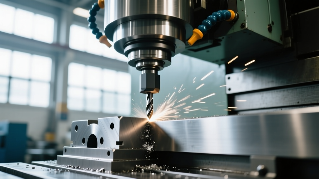
- Micro-Sparks at the Jaw Interface: Even when machining non-ferrous materials like 6061 aluminum or titanium, micro-sparks or a faint 'halo' of dust ejecting from the vise jaw-part interface indicates fretting. The part is slipping and re-seating thousands of times per minute.
- Chip Welding on the Fixture Base: If a cnc machine video shows chips being violently driven downward into the gap between the part and the fixture base, rather than evacuating outward, it indicates harmonic lift. The part is lifting, allowing chips underneath, and slamming back down, welding the chips to the fixture via extreme localized pressure.
- Spindle Load Meter Desync: While not strictly visual on the part, overlaying the machine's spindle load meter data with the video timeline often reveals that load spikes correlate perfectly with the exact moment the part shifts in the workholding, rather than when the tool engages the bulk material.
Case Study 2: Swiss-Type Medical Threading
A medical device manufacturer producing 316L stainless steel bone screws on a Citizen Cincom L32 Swiss-type lathe experienced intermittent pitch errors on the thread rolling operation. The part was held in a standard 16C collet with a carbide boring pad. The shop assumed the issue was related to tool wear or CNC servo lag.
By rigging a macro-lens camera system focused directly on the collet nose and shooting a specialized cnc machine video synchronized with the spindle encoder, the true root cause was exposed. At 10,000 RPM, the centrifugal force caused the 16C collet pads to expand outward by 0.0006 inches, slightly reducing the clamping force on the 0.250-inch diameter bar stock. Simultaneously, the heavy axial thrust of the thread rolling operation (measured at 320 lbs) overcame the diminished friction grip. The video clearly showed the bar stock being pushed back into the guide bushing by 0.004 inches during the rolling pass, resulting in a stretched thread pitch.
The solution involved switching to a dead-length collet system with a precision ground internal taper and applying a high-friction diamond-coated collet pad, which increased the axial holding force by 300% without requiring excessive drawbar tension that could deform the thin-walled collet.
| Workholding Metric | Static FEA Calculation | Video-Diagnosed Reality | Corrective Action Cost |
|---|---|---|---|
| Radial Deflection (Titanium) | 0.0001" (Acceptable) | 0.0018" (Catastrophic Lift) | $450 (Pitbull Clamps + Wax) |
| Axial Slippage (Swiss Turn) | 0.0000" (Zero Slip) | 0.0040" (Pitch Error) | $800 (Diamond Collet Pad) |
| Harmonic Resonance Frequency | 1,200 Hz (Predicted) | 410 Hz (Actual Excitation) | $0 (Spindle Speed Tuning) |
Implementing Dynamic Video Analysis in Your Shop
Integrating optical analysis into your workholding validation process does not require a dedicated metrology lab. However, capturing a usable diagnostic cnc machine video requires strict adherence to lighting and shutter parameters.
Camera Specifications for Fixture Monitoring
To capture chatter (300-800 Hz), your camera must shoot at a minimum of 2,000 fps. For macro-part lift and collet slippage, 240 fps to 500 fps is generally sufficient. The critical factor is not just frame rate, but shutter speed. At 2,000 fps, the maximum exposure time is 1/2,000th of a second. In the relatively dark environment of a CNC enclosure, this will result in a completely black image unless compensated with intense lighting.
Shops should invest in high-CRI (Color Rendering Index), flicker-free industrial LED arrays. Standard shop lights flicker at 120 Hz, which will create severe strobing and banding in high-speed footage, rendering the diagnostic data useless. A 100W flicker-free LED work light (such as those from Machine Light or similar industrial suppliers) positioned at a 45-degree angle to the cutting zone will provide the necessary photon density to allow for a 1/10,000s shutter speed, completely freezing the motion of the vibrating workpiece and the workholding jaws.
The ROI of Optical Workholding Validation
The cost of a single scrapped aerospace impeller or a batch of rejected medical implants far exceeds the time and equipment investment required for video analysis. By shifting from static assumptions to dynamic, video-verified workholding strategies, shops routinely reduce setup times, eliminate trial-and-run chatter tuning, and unlock aggressive cutting parameters that were previously deemed 'too risky' by static FEA models. The lens does not lie; it simply reveals the physics that static math ignores.