CNC Machine Oil Skimmer Specs for Spindle & Feed Rate Optimization
Learn how tramp oil degrades coolant heat transfer at high spindle speeds, and how to size a CNC machine oil skimmer to protect feed rate optimization.
The Thermodynamics of High-Speed Machining (HSM)
Optimizing spindle speeds and feed rates is fundamentally an exercise in thermal management. When machining aerospace aluminum (e.g., 7075-T6) at 18,000 RPM and 450 IPM, or pushing titanium Ti-6Al-4V at high-torque, low-RPM parameters, the shear zone generates immense localized heat. To prevent rapid flank wear on carbide inserts and thermal expansion of the workpiece, modern CNC relies on high-pressure flood coolant—often exceeding 1,000 PSI at the nozzle tip. According to Sandvik Coromant's machining guidelines, effective coolant penetration into the cutting zone is the single most critical variable for sustaining aggressive feed rates without triggering built-up edge (BUE) or tool fracture.
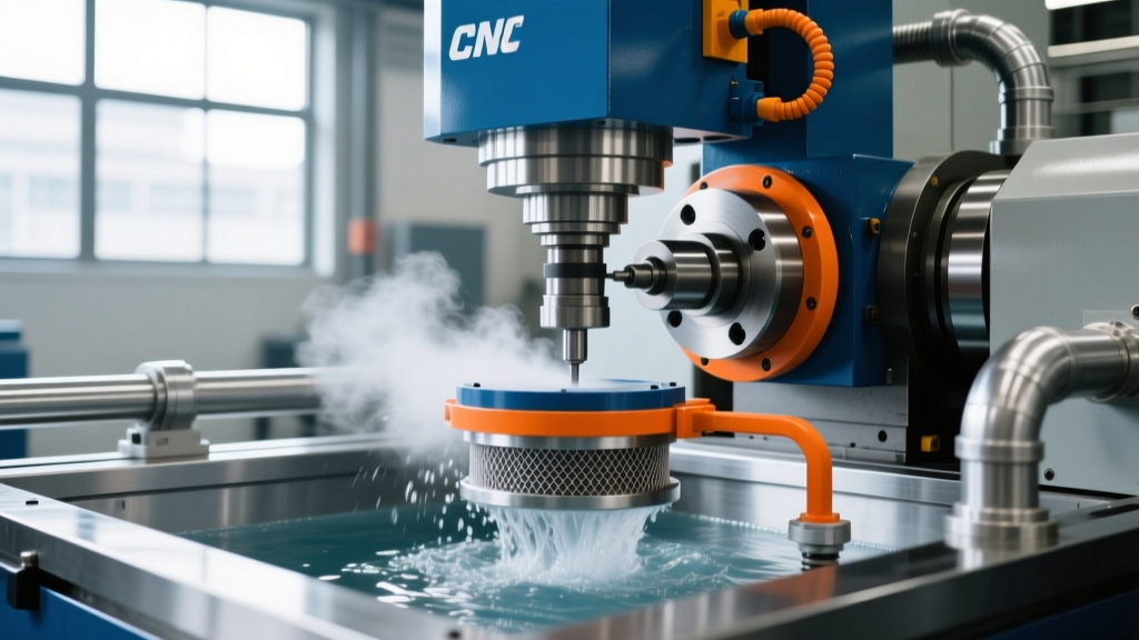
However, this thermal equation collapses if the coolant's surface tension is compromised. As way lubricants, spindle oils, and hydraulic fluids inevitably leak into the machine sump, they form a layer of tramp oil. This contamination directly sabotages your carefully calculated speeds and feeds by destroying the coolant's ability to wet the workpiece and evacuate chips.
Coolant Degradation: The Hidden Bottleneck in Feed Rate Optimization
Tramp oil is the silent killer of optimized machining parameters. When way lube (such as Mobil Vactra Oil No. 2, an ISO 68 viscosity fluid) enters the sump, it does not mix with the water-soluble coolant emulsion. Instead, it floats to the surface and coats the machine's internal plumbing, the workpiece, and the cutting tool.
⚠️ The 30% Heat Transfer PenaltyIndependent metallurgical studies show that a tramp oil layer as thin as 2 microns on a cutting tool can reduce the coolant's heat transfer coefficient by up to 30%. This creates a localized vapor barrier (similar to the Leidenfrost effect), causing the coolant to flash-boil before it can penetrate the shear zone. If you have optimized your feed rate based on pristine coolant assumptions, this 30% thermal penalty will result in immediate tool burn and poor surface finishes (exceeding 32 Ra µin).
To sustain high Material Removal Rates (MRR), a high-capacity CNC machine oil skimmer is not an optional accessory; it is a mandatory technical specification. Removing tramp oil restores the coolant's surface tension, allowing it to wet the tool and workpiece effectively, thereby validating your CAM software's optimized feed rate outputs.
Sizing the Right CNC Machine Oil Skimmer for Your Sump
Selecting a skimmer based solely on price or physical footprint is a common engineering error. The correct specification depends on the sump volume, the rate of way-lube consumption, and the machine's operational duty cycle. A 5-axis trunnion machine with a 120-gallon sump and rapid traverse rates will generate significantly more tramp oil than a standard 3-axis VMC with a 40-gallon sump.
The Turnover Formula
To size your skimmer, use the standard industrial turnover formula. The skimmer must be capable of processing the entire sump volume within a 4 to 6-hour window during continuous operation.
- Formula: Required GPH (Gallons Per Hour) = Total Sump Volume (Gallons) / Target Turnover Time (Hours)
- Example: A Haas VF-4SS with an 85-gallon sump targeting a 5-hour turnover requires a skimmer rated for at least 17 GPH.
Skimmer Technology Comparison Matrix
Different skimmer designs interact with coolant viscosity and chip contamination differently. Below is a technical comparison of the primary skimmer types used in modern CNC environments:
| Skimmer Type | Mechanism | Typical Removal Rate | Best Application Scenario |
|---|---|---|---|
| Belt Skimmer (e.g., Abanaki Model 8) | Continuous oleophilic belt passes through fluid; wipers scrape oil. | 12 - 40 GPH | Large central coolant systems, heavy chip environments, high-viscosity way lubes. |
| Tube Skimmer (e.g., Oil Skimmers Inc. 6V) | Infinite polymer tube snakes through sump; ceramic scraper removes oil. | 6 - 12 GPH | Individual VMC sumps, tight spaces, coolants with high suspended fines. |
| Disk Skimmer | Rotating oleophilic disks; fixed wipers scrape both sides. | 8 - 20 GPH | Shallow sumps, low-volume tramp oil leaks, Swiss-type lathes. |
| Coalescer / Band | Forces fluid through media to merge micro-droplets before skimming. | 50 - 200+ GPH | High-pressure (1000+ PSI) coolant systems where tramp oil is heavily emulsified. |
Step-by-Step Sump Integration for 5-Axis and Multi-Pallet Machines
Installing a CNC machine oil skimmer without considering fluid dynamics will result in poor oil capture. Tramp oil must be guided to the skimmer's intake. Follow this integration protocol for advanced CNC setups:
- Install Sump Baffles: Weld or bolt steel baffles inside the sump to create a 'quiet zone' near the skimmer intake. This prevents the high-velocity coolant return from dragging surface oil back into the main reservoir.
- Position the Skimmer Intake: Mount the skimmer at the highest point of the coolant return flow, downstream of the chip conveyor discharge. The returning fluid acts as a natural conveyor belt, pushing floating tramp oil directly into the skimmer's weir or belt path.
- Implement a Fluid Level Float Switch: High-speed machining consumes coolant through evaporation and part carry-off. If the coolant level drops below the skimmer's intake, the skimmer will pull air, rendering it useless and potentially burning out the motor. Wire a secondary float switch to trigger an alarm or auto-fill valve.
- Configure the Discharge Chute: Ensure the skimmer's discharge chute is angled at a minimum of 30 degrees into the collection drum. Tramp oil mixed with fine aluminum or titanium chips can become highly viscous; a shallow angle will cause the discharge to clog and overflow back into the sump.
Real-World Troubleshooting: When Optimized Feeds Still Burn Tools
Even with a correctly sized CNC machine oil skimmer running 24/7, machinists sometimes experience tool burn when executing optimized high-speed toolpaths. Before reducing your feed rate or spindle speed, investigate these non-obvious failure modes:
1. Emulsion Split from High-Pressure Shear
Coolant pumps operating at 1,000 PSI generate massive mechanical shear. Over time, this shear can break the chemical bonds of the coolant emulsion, causing the base oil to separate and float to the top. Your skimmer will remove this fluid, but it is removing active coolant, not just tramp oil. Fix: Switch to a high-stability synthetic or semi-synthetic coolant (e.g., Master Fluid Solutions TRIM MicroSol) designed specifically for high-pressure shear environments, and monitor concentration daily with a digital refractometer.
2. Way Lube Viscosity Mismatch
If a machine is equipped with an ISO 220 way lube (often used on heavy-duty box-way machines) but is being used for high-speed aluminum milling, the heavy oil will not float cleanly. It tends to suspend in the coolant as a thick mayonnaise-like sludge that blinds tube and belt skimmers. Fix: Consult the machine builder to verify if downgrading to an ISO 68 way lube is permissible for your specific load profiles, or install a coalescing pre-filter before the skimmer.
3. Bacterial Consumption of Emulsifiers
Tramp oil blocks oxygen from entering the coolant, creating an anaerobic environment where sulfate-reducing bacteria thrive. These bacteria consume the emulsifiers that keep the coolant stable. As noted in OSHA's Metalworking Fluids guidelines, bacterial growth not only poses severe respiratory health risks but also destroys the fluid's lubricity. If your coolant smells like rotten eggs, your feed rate optimization will fail due to microscopic welding on the tool edge. Fix: Shock-treat the sump with a broad-spectrum biocide, run the skimmer continuously to remove the dead oil layer, and install an ozone or UV inline sterilizer.
Summary: The Symbiosis of Speeds, Feeds, and Skimmers
You cannot isolate spindle speed and feed rate optimization from the physical state of your cutting fluid. Pushing the limits of MRR requires flawless thermal evacuation. By specifying the correct CNC machine oil skimmer based on sump turnover rates, integrating it with proper fluid dynamics in mind, and monitoring for emulsion shear, you protect your tooling investment and ensure your CAM-generated feed rates perform exactly as simulated on the shop floor.