Optimizing the CNC Machine Manufacturing Process: Speed & Feed Rates
Master the CNC machine manufacturing process with technical guides on spindle speed, feed rate optimization, chip thinning, and HEM toolpaths.
The intersection of spindle speed and feed rate dictates the success of any modern CNC machine manufacturing process. While basic machinist manuals provide static lookup tables for speeds and feeds, achieving optimal cycle times, maximizing tool life, and maintaining tight tolerances requires a dynamic understanding of cutting physics, tool deflection, and machine rigidity. Optimizing these parameters is not about finding a single "correct" number; it is about balancing thermal management, chip evacuation, and radial cutting forces.
The Physics of Chip Formation: Beyond Basic Formulas
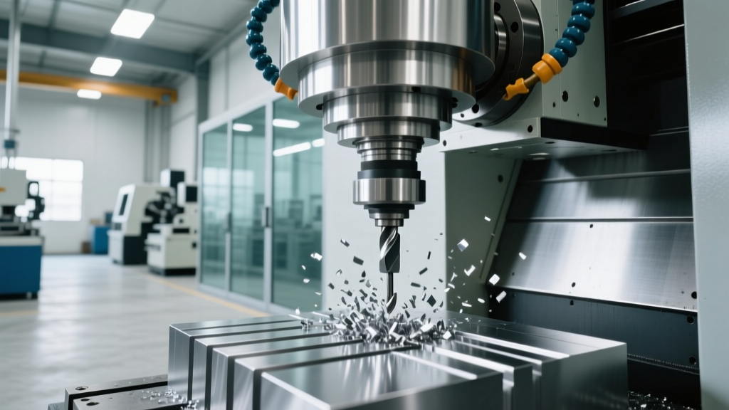
At the core of the CNC machine manufacturing process is chip formation. The goal is to generate a chip thick enough to carry heat away from the cutting zone, but thin enough to prevent excessive tool deflection. This balance is governed by Surface Feet per Minute (SFM) and Inches Per Tooth (IPT).
Core Speed & Feed Equations
RPM Calculation:
RPM = (SFM × 3.82) / Tool Diameter
Feed Rate (IPM) Calculation:
IPM = RPM × Number of Flutes × IPT
Note: The constant 3.82 is derived from (12 / π), converting feet to inches and accounting for the circumference of the tool.
The Chip Thinning Phenomenon
When utilizing modern High-Efficiency Milling (HEM) toolpaths, the Radial Depth of Cut (RDOC) is often less than 50% of the tool diameter. In these scenarios, the chip thickness is physically thinner than the programmed IPT due to the geometry of the circular toolpath. If you do not compensate for chip thinning, the tool will rub rather than cut, leading to rapid work hardening and premature edge failure.
To calculate the adjusted IPT when RDOC is less than 50% of the tool diameter (D):
IPTadjusted = IPT / sin(arccos(1 - (2 × RDOC / D)))
For example, if you are using a 1/2-inch endmill with an RDOC of 0.050 inches (10% stepover) and a base IPT of 0.004, the adjusted IPT must be increased to approximately 0.010 to maintain the same effective chip thickness and thermal load on the carbide edge.
Material-Specific Speed and Feed Baselines
The following matrix provides baseline parameters for a standard 1/2-inch (12.7mm) 4-flute solid carbide endmill with an AlTiN or TiSiN coating. These values assume a rigid CNC machining center (e.g., Haas VF-2SS or DMG MORI CMX V) with a minimum of 20 IPM rapid traverse capability.
| Material | Target SFM | IPT (Slotting) | IPT (HEM 10% RDOC) | Coolant Strategy |
|---|---|---|---|---|
| 6061-T6 Aluminum | 1,800 - 2,500 | 0.0035" | 0.0085" | Flood or MQL |
| 304 Stainless Steel | 250 - 350 | 0.0020" | 0.0050" | High-Pressure (1000 PSI) |
| P20 Mold Steel | 300 - 400 | 0.0025" | 0.0060" | Air Blast / Mist |
| Ti-6Al-4V (Titanium) | 120 - 180 | 0.0015" | 0.0040" | Through-Tool (1500 PSI) |
Data synthesized from Harvey Tool technical guides and updated for modern variable-helix carbide geometries.
Troubleshooting Chatter and Tool Deflection
Even with mathematically perfect speeds and feeds, the physical realities of the CNC machine manufacturing process introduce variables like tool stickout, holder runout, and machine damping. Use this diagnostic framework to adjust parameters when surface finish degrades or audible chatter occurs.
Diagnostic Decision Tree: Edge Failure & Chatter
- Symptom: High-pitched squeal or harmonic ringing (Chatter)
- Cause: Radial cutting forces exceeding tool/machine rigidity.
- Fix 1: Reduce RDOC by 20% and increase feed rate to maintain MRR (Material Removal Rate).
- Fix 2: Adjust RPM up or down by 10-15% to change the harmonic frequency and exit the chatter zone.
- Symptom: Built-Up Edge (BUE) on Aluminum or Stainless
- Cause: SFM is too low, or IPT is too light, causing the material to weld to the cutting edge.
- Fix: Increase SFM by 15% and verify chip thickness is exceeding the tool's edge hone (usually 0.0002" - 0.0005").
- Symptom: Rapid Flank Wear (Carbide tools in Steel/Titanium)
- Cause: Excessive thermal load; heat is not being carried away by the chip.
- Fix: Decrease SFM by 10%, increase IPT slightly, and ensure coolant is directly penetrating the cutting zone.
Integrating High-Pressure Coolant (HPC) and Adaptive Toolpaths
In advanced CNC machining environments, optimizing the manufacturing process requires pairing speeds and feeds with adaptive toolpaths and high-pressure coolant systems. Traditional flood coolant (typically 30-50 PSI) merely washes chips away from the workpiece. It cannot penetrate the localized vapor barrier created at the cutting edge when machining high-temperature alloys like Inconel 718 or Ti-6Al-4V.
The Role of Through-Tool High-Pressure Coolant
Modern machining centers equipped with 1,000 to 2,000 PSI through-spindle coolant systems fundamentally change the speed and feed envelope. According to Sandvik Coromant's metal cutting research, directing high-pressure coolant precisely at the shear zone forces the chip to curl tighter and break earlier. This allows machinists to increase the SFM on titanium alloys by up to 20% without accelerating crater wear on the carbide insert, because the fluid physically lifts the chip off the rake face.
Adaptive Clearing and Dynamic Motion
Software algorithms like Mastercam's Dynamic Motion or Fusion 360's Adaptive Clearing maintain a constant tool engagement angle. By keeping the RDOC strictly controlled (often between 5% and 12% of the tool diameter), the CNC machine manufacturing process can utilize the full Axial Depth of Cut (ADOC)—often 1.5x to 2x the tool diameter.
Because the radial forces are kept incredibly low, the tool can be fed at much higher IPT values without deflecting. A 1/2-inch endmill that would fail instantly if slotting 304 Stainless at 15 IPM can easily run at 45 IPM using an adaptive toolpath with a 0.040" RDOC and a 0.750" ADOC, resulting in a net increase in material removal rate and a 300% increase in tool life.
Machine Rigidity: The Ultimate Bottleneck
Theoretical speeds and feeds are useless if the machine tool cannot physically support the cutting forces. When programming a CNC machine manufacturing process, you must account for the spindle taper and machine mass.
- CAT40 / BT40 Tapers: Common on mid-range vertical machining centers (e.g., Haas VF series, Brother Speedio). These lack the dual-contact rigidity required for heavy roughing. Stick to HEM toolpaths with low RDOC and high feed rates to minimize radial pressure that pulls the toolholder out of the spindle.
- HSK-A63 / CAT50 Tapers: Found on heavy-duty mills (e.g., Makino a61nx, DMG MORI DMC H). The dual-contact face-and-taper clamping of HSK allows for aggressive slotting and high-torque roughing. Here, you can utilize lower SFM and heavier IPT values to maximize spindle horsepower (often 30HP+) rather than relying solely on high-RPM light cuts.
Ultimately, optimizing spindle speed and feed rate is an iterative process. Start with the mathematical baselines provided by tooling manufacturers, monitor the acoustic signature of the cut, measure the resulting chips for proper color and thickness, and adjust dynamically based on the specific harmonic profile of your machine tool.