CNC Machine History: Troubleshooting Modern Composite Cutting Errors
Explore cnc machine history and modern troubleshooting for composite cutting. Fix delamination, tool wear, and dust issues in CFRP and GFRP machining.
The Evolution of Composite Machining in CNC Machine History
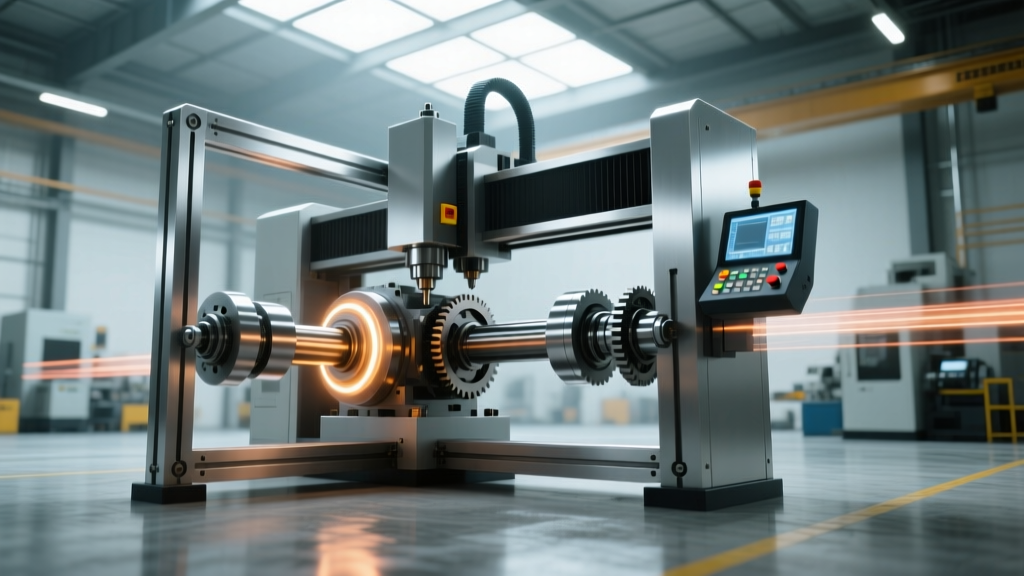
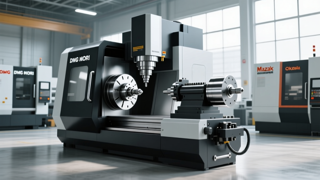
When tracing cnc machine history, the integration of advanced composite materials like Carbon Fiber Reinforced Polymer (CFRP) and Glass Fiber Reinforced Polymer (GFRP) represents one of the most significant disruptive shifts in manufacturing. Early 3-axis CNC mills from the 1980s and 1990s relied on high-speed steel (HSS) and standard micro-grain carbide tooling. These setups catastrophically failed when introduced to aerospace-grade carbon fibers, suffering from extreme abrasive wear, severe delamination, and rapid thermal degradation of the resin matrix.
Modern composite cutting requires a fundamental departure from traditional metalworking parameters. Today's 5-axis routers and high-frequency spindle systems are engineered specifically to manage the anisotropic nature of composites. However, even with advanced SME-recognized material engineering protocols, shop floors frequently encounter cutting errors, spindle failures, and workholding issues. This guide provides actionable troubleshooting frameworks for resolving the most common composite machining defects and equipment failures encountered in modern production environments.
Diagnostic Matrix: Identifying and Resolving Composite Cutting Failures
Composite materials do not machine like metals; they fracture and shear. Misdiagnosing a surface defect as a tooling issue when it is actually a workholding or parameter problem leads to costly scrap. Use the following diagnostic matrix to isolate the root cause of your cutting errors.
| Symptom / Defect | Root Cause Analysis | Technical Fix & Parameter Adjustment |
|---|---|---|
| Top/Bottom Delamination | Incorrect tool geometry; excessive axial cutting forces pushing/pulling the plies apart. | Switch to a compression router bit (e.g., Onsrud 63-700 series). Ensure spindle runout is below 0.0002 inches. |
| Rapid Abrasive Tool Wear | Standard carbide used instead of diamond-coated tooling; excessive surface speed (SFM). | Upgrade to CVD (Chemical Vapor Deposition) diamond-coated end mills. Reduce RPM by 10-15% to lower thermal load. |
| Fraying / Kevlar 'Fuzzing' | Shear angle too low; tool pushing fibers rather than slicing them. | Use left-hand shear, right-hand flute tooling. Increase feed rate to maintain a chip load above 0.008 inches. |
| Resin Matrix Melting / Smearing | Poor chip evacuation; tool dwelling in the cut; lack of compressed air blast. | Implement high-pressure air blast (never liquid coolant). Increase feed rate to evacuate heat via chips. |
| Chatter Marks on Edge | Insufficient vacuum hold-down; thin composite sheet vibrating at high spindle frequencies. | Upgrade to a phenolic resin spoilboard; increase vacuum pump CFM; add mechanical toggle clamps at perimeters. |
Tackling Delamination and Fraying
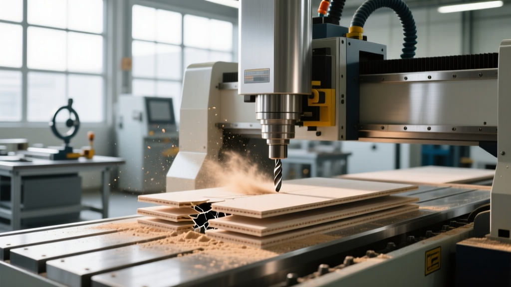
Delamination is the most critical failure mode in CFRP machining. It occurs when the axial cutting force exceeds the interlaminar shear strength of the resin. Standard up-cut spirals pull the bottom plies upward, causing bottom delamination, while down-cut spirals push the top plies downward, causing top splintering.
The Fix: Utilize a compression bit where the lower flutes pull chips up and the upper flutes push chips down, effectively clamping the material together during the cut. For materials thicker than 0.5 inches, ensure the compression zone of the tool matches the material thickness exactly. If the tool's compression zone is longer than the material, the opposing vector forces will tear the laminate apart.
Managing Abrasive Tool Wear
Carbon and glass fibers are highly abrasive, acting like microscopic grinding wheels against cutting edges. Uncoated carbide tools may last only 10 to 15 linear feet of cutting in CFRP before edge breakdown causes severe fraying.
The Fix: Polycrystalline Diamond (PCD) or CVD diamond-coated tooling is mandatory. PCD insert routers can achieve 100+ times the tool life of standard carbide. However, PCD tools are brittle. If your CNC machine experiences frequent micro-crashing or spindle runout exceeds 0.0003 inches, PCD edges will chip. Always verify tool holder concentricity before running high-cost diamond tooling.
Spindle & Drive Troubleshooting: The Conductive Dust Threat
One of the most overlooked aspects of composite CNC maintenance is the nature of the dust generated. Carbon fiber dust is not just a respiratory hazard; it is highly electrically conductive and microscopically abrasive. In the context of modern CNC machine history, the transition to sealed, air-purged spindles was driven entirely by the need to keep carbon dust out of precision ceramic bearings and VFD (Variable Frequency Drive) electronics.
Step-by-Step Spindle Seal Inspection and Repair
If your spindle is exhibiting increased vibration, elevated operating temperatures, or throwing VFD over-current alarms, carbon dust ingress is the primary suspect.
- Check Purge Air Pressure: Modern HSK63F or ISO30 composite spindles require a continuous positive air purge to the labyrinth seals. Verify the purge air pressure is maintained strictly between 1.5 and 2.0 bar (21-29 PSI). A drop below 1.5 bar allows microscopic carbon particles to bypass the seal.
- Inspect the Labyrinth Seal: Remove the tool holder and visually inspect the spindle nose. If you see black, greasy residue around the shaft opening, the internal labyrinth has failed, and carbon dust has mixed with the bearing grease.
- Measure Runout: Insert a precision 1/2-inch carbide blank. Mount a dial indicator with 0.0001-inch resolution at the tool tip. Rotate the spindle by hand. Runout exceeding 0.0003 inches indicates pitted ceramic bearings requiring a full spindle rebuild.
- Seal Electrical Cabinets: Carbon dust infiltrates cabinet vents, causing short circuits in servo drives. Ensure all electrical enclosures are sealed and equipped with positive-pressure filtered air systems. Replace standard foam filters with HEPA-grade media rated for conductive particulates.
⚠️ Critical Health & Safety Warning
Machining CFRP and GFRP generates airborne particulates that pose severe respiratory risks. According to the CDC NIOSH Hierarchy of Controls, relying solely on PPE is insufficient. You must implement engineering controls, specifically localized exhaust ventilation (LEV) capturing a minimum of 1200 CFM directly at the cutting hood, paired with ambient HEPA filtration systems to capture escaped micro-fibers.
Workholding and Extraction: Beyond Standard MDF Spoilboards
Standard MDF (Medium Density Fiberboard) spoilboards used in wood and plastics routing are entirely unsuitable for composite materials. The micro-abrasive nature of carbon dust rapidly degrades MDF, causing it to lose porosity and vacuum holding power within days. Furthermore, the static electricity generated by cutting composites causes dust to cling to the material and the machine, interfering with laser tool setters and vision systems.
Upgrading the Vacuum System
To troubleshoot poor hold-down and premature spoilboard failure, transition to a specialized composite workholding setup:
- Spoilboard Material: Replace MDF with a high-density phenolic resin board or a specialized synthetic composite board (e.g., Trucore). These materials resist abrasive wear and maintain consistent vacuum permeability.
- Static Dissipation: Install ionizing air bars near the cutting zone to neutralize static charges. This prevents carbon dust from clinging to the cut edges, which can interfere with downstream automated inspection.
- Vacuum Pump Sizing: Composite routing requires higher vacuum pressure (inches of Mercury, inHg) rather than just volume (CFM) due to the use of smaller, dedicated pod fixtures. Ensure your regenerative blower can maintain a minimum of 22 inHg at the pump inlet during high-feed-rate operations.
Advanced Parameters for 2026 Composite Routing
Establishing a baseline parameter sheet is critical for troubleshooting. If your machine is producing poor edge quality, verify your settings against these industry-standard baselines for a 1/2-inch diameter CVD diamond compression router:
Carbon Fiber Reinforced Polymer (CFRP)
- Spindle Speed: 18,000 - 22,000 RPM
- Feed Rate: 120 - 180 IPM (Inches Per Minute)
- Chip Load: 0.006" - 0.008" per flute
- Depth of Cut: Maximum 1.5x tool diameter per pass to minimize deflection.
Glass Fiber Reinforced Polymer (GFRP)
- Spindle Speed: 15,000 - 18,000 RPM (Glass is more abrasive than carbon; lower speeds reduce thermal breakdown of the tool coating).
- Feed Rate: 100 - 140 IPM
- Chip Load: 0.008" - 0.010" per flute (Thicker chips carry heat away from the resin matrix).
Aramid (Kevlar) Composites
Kevlar is notoriously difficult to machine due to its high tensile strength and tendency to fray. Standard compression bits will fail. You must use specialized left-hand shear, right-hand flute tooling designed to slice the fibers cleanly. Reduce RPM to 10,000 - 12,000 and aggressively increase the feed rate to prevent the tool from pushing the flexible fibers aside rather than cutting them.
Summary: Proactive Maintenance for Composite Shops
Troubleshooting composite cutting errors requires looking beyond the toolpath. By understanding the historical limitations that shaped modern CNC machine history, operators can appreciate why specialized tooling, air-purged spindles, and rigorous dust extraction are non-negotiable. Implement strict runout checks, transition to CVD diamond tooling, and maintain positive-pressure electrical cabinets to ensure your composite machining operations remain precise, safe, and highly profitable.