CNC Electric Discharge Machine Controller Training for Operators
Master CNC electric discharge machine controllers with our operator training guide. Learn interface types, setup best practices, and troubleshooting.
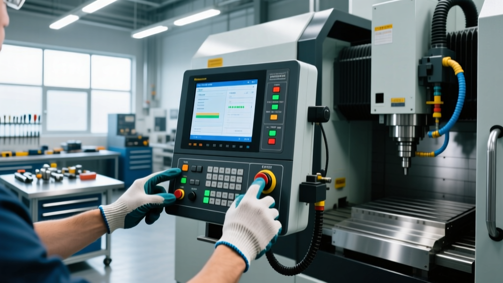
Operating a CNC electric discharge machine (EDM) requires a fundamentally different cognitive approach than standard 3-axis CNC milling. While milling controllers focus on toolpath vectors and spindle loads, EDM controllers manage dielectric fluid dynamics, spark gap voltages, and independent U/V axis taper geometries. For operators transitioning into wire EDM or sinker EDM roles, mastering the human-machine interface (HMI) is the primary barrier to achieving consistent, unattended machining cycles.
This training guide dissects the current-generation controller interfaces dominating the 2026 market, providing actionable frameworks for navigating Auto Wire Threading (AWT) subroutines, managing complex taper datums, and resolving dielectric-specific alarm codes.
Decoding the Big Three: Proprietary vs. Fanuc EDM Interfaces
The user experience varies drastically depending on the machine builder. Understanding the architectural philosophy of your specific controller is the first step in reducing setup times and preventing wire breakage.
| Controller Architecture | Interface Paradigm | AWT Subroutine UI | Taper Control Logic |
|---|---|---|---|
| Sodick LP5 / LP2 | 19-inch capacitive touch, Heart NC conversational | Visual jet-alignment wizard; auto-recovery mapping | Integrated 3D taper verification with collision detection |
| Mitsubishi M800EDM | Touch panel with Digital Generator monitoring dashboards | Submerged/Flush toggle with real-time fluid pressure graphs | Variable taper height datum input via soft-keys |
| Fanuc Series 31i-B | iHMI (Intelligent HMI) with tablet-like swipe navigation | Parameter-driven (e.g., Param 4902) with macro overrides | U/V axis independent coordinate system overlays |
Operators moving from Fanuc milling controls to Fanuc EDM systems often struggle with the iHMI's heavy reliance on custom macro variables for spark gap control. Conversely, Sodick's proprietary interface abstracts much of the G-code, relying instead on visual wizards that require the operator to understand the physical physics of the flush nozzles rather than the code itself.
Step-by-Step: Navigating the Auto Wire Threading (AWT) Interface
Auto Wire Threading is the most critical automated function on a wire EDM. A failed thread halts production and ruins unattended shifts. The controller interface requires precise input regarding the threading environment.
- Select the Threading Environment (Submerged vs. Flush): On Mitsubishi and Sodick interfaces, you must explicitly tell the controller if the start hole is submerged in dielectric fluid. Submerged threading requires the UI to activate the lower flush jet to create a localized vortex, guiding the wire. Flush threading relies on upper jet pressure alone.
- Define the Wire Annealing Parameters: Access the AWT setup menu. Set the annealing current based on wire diameter. For 0.010-inch (0.25mm) brass wire, standard annealing time is 0.8 to 1.2 seconds. Over-annealing makes the wire too brittle; under-annealing prevents the chopper from cutting a clean, tapered tip.
- Map the Auto-Recovery Search Pattern: If a wire breaks mid-cut, the controller must find the path. In the Fanuc iHMI, navigate to the Wire Recovery screen. Set the search radius to 0.020 inches and the reverse-cut feed rate to 50% of normal. This prevents the wire from jamming into the kerf during the backtrack.
Mastering U/V Axis Taper Controls and Datums
Standard CNC mills operate on X, Y, and Z axes. Wire EDMs add U and V axes to control the upper wire guide, enabling taper cuts. Misunderstanding how the controller calculates the taper datum is the leading cause of scrapped parts and snapped wires.
"The most common mistake novice EDM operators make is assuming the Z-axis workpiece top is the taper pivot point. The controller needs the exact Z-height where the taper angle begins to transition, otherwise the U/V axes will over-travel and snap the wire on sharp internal corners."
— Advanced EDM Programming Guidelines, Mitsubishi EDM Technical Docs
The Taper Height Datum Workflow
When setting up a variable taper cut (e.g., a 15-degree taper that transitions to 0 degrees), follow this exact interface sequence:
- Step 1: Touch off the Z-axis on the top of the workpiece. Set this as your Z-Work Zero.
- Step 2: Open the Taper Condition page in the controller.
- Step 3: Input the Taper Height. This is the Z-distance from the workpiece top where the taper physically starts. If the part has a 0.100-inch straight land before the taper begins, input Z-0.100.
- Step 4: Verify the U/V travel limits on the graphical preview screen. If the U/V axes hit their physical limit (usually around ±2.0 inches), the controller will throw a soft-limit alarm before the cycle starts.
Critical Controller Alarms and Operator Responses
EDM controllers generate highly specific alarms related to the spark gap and dielectric fluid. Operators must move beyond simply pressing 'Reset' and understand the root cause indicated by the HMI.
- Alarm: Short Circuit / Gap Voltage Zero (Fanuc 400-series / Sodick E-Code): The wire is physically touching the workpiece. Action: Do not simply reverse. Reduce the machining feed rate by 20% in the override menu, increase the flush pressure, and command a 0.050-inch retract. If the short persists, the kerf is likely pinched due to residual material stress; activate the controller's 'Anti-Electrolysis' and 'Kerf Widening' subroutines.
- Alarm: Wire Breakage Detection (AWT Sensor Fault): The tension sensor has dropped below the 800g threshold. Action: Check the lower flush nozzle for debris. A clogged lower nozzle creates a vacuum effect that pulls the wire off the lower guide, triggering a false breakage alarm on the controller.
- Alarm: Dielectric Fluid Conductivity High: The resin bed is exhausted or the water temperature is fluctuating. Action: Check the chiller unit interface. EDM water must be held at exactly 68°F (20°C). A 2-degree rise in temperature will alter the spark gap by up to 0.0002 inches, ruining tight-tolerance die inserts.
Best Practices for Controller Maintenance and Backup
The EDM controller stores thousands of critical parameters, including wire tension maps, generator settings, and absolute encoder positions. A dead controller battery or corrupted memory card results in days of downtime.
1. Absolute Encoder Battery Replacement: Modern EDMs use absolute pulse coders on the X, Y, U, and V axes. These require a dedicated battery (typically a Panasonic BR2032 or equivalent lithium-thionyl chloride cell) to retain position data when powered off. Rule: Replace these batteries annually, only while the main machine breaker is ON. Replacing them while powered off will wipe the absolute position data, requiring a full machine re-homing procedure by a service technician.
2. SRAM and Parameter Backups: Do not rely on manual USB backups. Configure the controller's Ethernet port to push a daily encrypted backup to your shop's local server. On Fanuc iHMI systems, navigate to System -> Data Server -> Auto Backup and schedule it for 2:00 AM. Ensure the backup includes the PMC (Programmable Machine Controller) ladder logic and the custom macro variables specific to your shop's wire types.
Mastering the CNC electric discharge machine interface is an ongoing process of correlating digital inputs with physical spark erosion. By respecting the nuances of AWT subroutines, accurately defining taper datums, and responding intelligently to gap-voltage alarms, operators can transform the EDM from a high-maintenance bottleneck into a highly profitable, lights-out manufacturing asset.