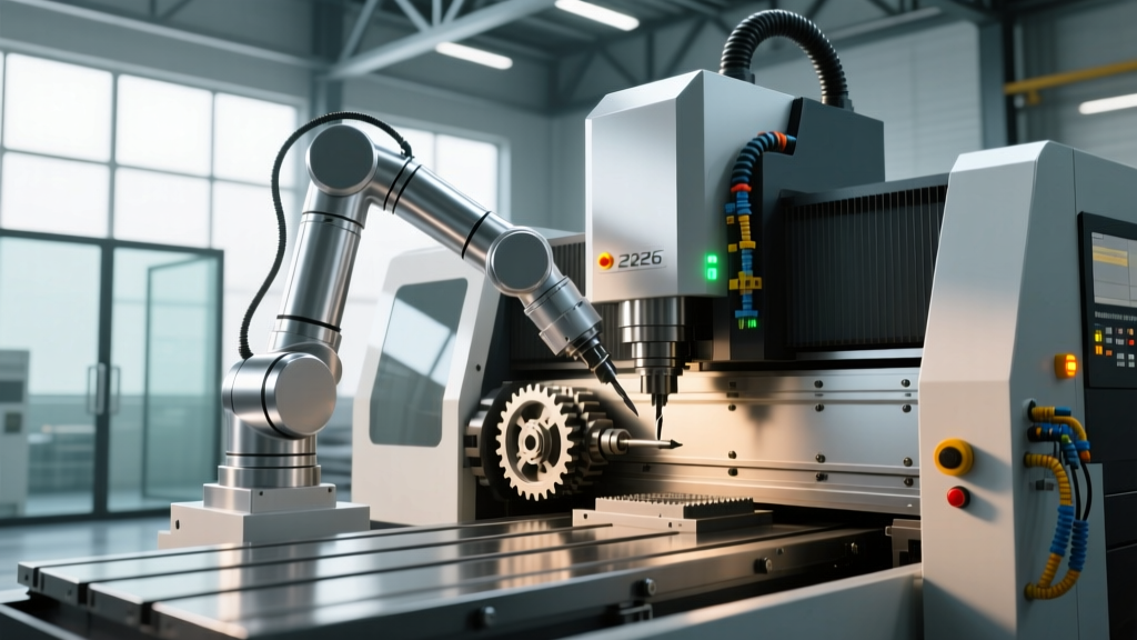
Automatic Tool Changer in CNC Machine: 2026 Power Setup Guide
Master the electrical requirements for an automatic tool changer in CNC machine setups. Explore 2026 power specs, regenerative drives, and voltage tuning.
The Transient Load Reality of Modern ATCs
The shift from 5-second to sub-1.2-second tool-to-tool change times has fundamentally altered the electrical architecture of modern machining centers. When facility planners and maintenance engineers specify an automatic tool changer in CNC machine environments, the primary focus often lands on mechanical clearance and pneumatic pressure. However, the electrical power setup is the actual bottleneck for reliability. High-speed, servo-driven carousel systems—such as the 40+1 side-mount magazines on Haas SS series or the HSK-63 chain-type ATCs on Hermle C-series machines—generate massive transient electrical loads that can destabilize sensitive spindle drives if the power infrastructure is undersized.
In 2026, the integration of Silicon Carbide (SiC) MOSFETs in servo amplifiers has improved switching speeds and reduced heat, but it has simultaneously introduced high-frequency harmonic noise into the DC bus. Properly designing the electrical feed for the ATC requires managing inrush currents, mitigating regenerative voltage spikes, and ensuring pristine grounding topology to protect the 5V differential RS-422 encoder signals that dictate carousel positioning.
⚠️ Critical Voltage Drop Warning: A voltage drop exceeding 8% during the peak acceleration phase of an ATC arm swing will cause the servo amplifier to register a DC bus undervoltage fault. This typically manifests as a Fanuc Alarm 401 (Servo Alarm) or a Haas Alarm 162, halting production and potentially leaving a tool half-seated in the spindle taper.Core Electrical Requirements for 2026 ATC Systems
Modern CNC facilities must adhere to strict voltage tolerances. According to NEMA MG-1 standards for motors and generators, industrial equipment is designed to operate successfully at rated load with voltage variations not exceeding ±10% of the rated nameplate voltage. For a standard 480V 3-phase system, the absolute operational window is 432V to 528V. However, ATC servo drives require a much tighter band (±5%) to maintain the precise torque control needed for high-speed deceleration.
| ATC Class | Typical Magazine Type | Servo Continuous Draw | Peak Inrush (200ms) | Required Circuit Breaker |
|---|---|---|---|---|
| Standard 40-Taper | Umbrella / Arm (20-24 tools) | 2.5 kW (5A) | 18A | 15A Motor Rated |
| High-Speed 40-Taper | Side-Mount (30-50 tools) | 4.0 kW (8A) | 32A | 20A Motor Rated |
| HSK-63 / HSK-100 | Chain / Matrix (60-120+ tools) | 7.5 kW (15A) | 65A | 30A Motor Rated |
Mitigating Inrush Current and Regenerative Feedback
The most misunderstood aspect of ATC power setup is regenerative feedback. When a heavily loaded 60-tool chain magazine decelerates from 120 RPM to a hard stop in under 0.4 seconds, the kinetic energy is converted back into electrical energy. The servo motor acts as a generator, pumping current back into the drive's DC bus.
The Active Front End (AFE) vs. Braking Resistor Debate
In legacy systems, this excess energy was burned off as heat through a dynamic braking resistor (typically a 100-ohm, 1.5kW wirewound resistor mounted on the cabinet wall). While cheap, this wastes energy and increases cabinet ambient temperatures, forcing higher HVAC loads.
The 2026 standard for premium machining centers utilizes an Active Front End (AFE) drive architecture. An AFE uses an IGBT bridge to push the regenerative energy cleanly back into the facility's 3-phase grid at a unity power factor. When sizing your electrical panel, if your machine utilizes a standard diode-bridge rectifier with a braking resistor, you must account for the localized heat dissipation in your cabinet cooling calculations. If the machine uses an AFE, you must ensure your facility's main isolation transformer can handle bi-directional power flow without tripping reverse-power relays.
Smart Power Conditioning and IoT Monitoring
As manufacturing aligns with the Department of Energy's Advanced Manufacturing initiatives, power monitoring has moved from the main facility switchgear directly to the machine tool enclosure. Installing a localized IoT power meter—such as the Schneider Electric PowerLogic PM5xxx series—on the ATC's dedicated branch circuit provides critical predictive maintenance data.
- Harmonic Distortion Tracking: SiC drives generate high-frequency noise. Monitoring Total Harmonic Distortion (THD) ensures it stays below the IEEE 519 recommended 5% limit, preventing interference with nearby CMMs or laser trackers.
- Micro-Interruption Logging: Capturing voltage sags lasting less than 16 milliseconds that are invisible to standard SCADA systems but cause ATC encoder miscounts.
- Phase Imbalance Alerts: A phase voltage imbalance of just 2% can cause a 15% temperature rise in the ATC servo motor windings, degrading the insulation and leading to premature motor failure.
Step-by-Step: Sizing the Isolation Transformer
Never rely solely on the utility drop for a high-speed ATC machine. An isolation transformer with a Delta primary and Wye secondary provides a localized, clean ground reference and mitigates common-mode noise. Here is the exact framework for sizing:
- Calculate Total kVA: Sum the continuous kVA of the spindle, coolant pumps, and ATC servos. (e.g., 25 kVA Spindle + 3 kVA Pumps + 5 kVA ATC = 33 kVA).
- Apply the Inrush Multiplier: Identify the highest starting load (usually the ATC carousel or spindle). Multiply this specific load by 1.5 to account for transformer impedance voltage drop during startup.
- Add the Safety Margin: Multiply the final sum by 1.25 to allow for future peripheral additions (e.g., adding a high-pressure coolant pump later).
- Select Standard Size: For a calculated 44.5 kVA, specify the next standard transformer size: 45 kVA or 60 kVA. Always oversize to the next standard NEMA rating to prevent core saturation.
Grounding Topology and Signal Integrity
The mechanical precision of an automatic tool changer in CNC machine setups is entirely dependent on the integrity of its absolute encoders. These encoders communicate via high-speed serial protocols (like Fanuc's serial interface or Siemens DRIVE-CLiQ) which are highly susceptible to electromagnetic interference (EMI).
Adhering to OSHA electrical safety and grounding guidelines is the baseline, but CNC signal integrity requires a dedicated high-frequency grounding strategy. You must implement a single-point 'star' grounding topology inside the electrical cabinet. All ATC servo motor ground cables, encoder shield drains, and cabinet backplane grounds must terminate at a single, heavy copper busbar connected directly to the facility's earth ground electrode. Daisy-chaining grounds through terminal blocks creates ground loops, which inject 60Hz noise into the encoder signal, resulting in random 'Tool Unclamped' or 'Carousel Position Error' alarms mid-cycle.
'In 2026, the most common cause of unexplained ATC crashes isn't mechanical wear or pneumatic leaks; it's improper shield termination on the servo encoder cables allowing VFD switching noise to corrupt the absolute position data.'
— Senior Field Service Engineer, Tier-1 CNC OEM
Frequently Asked Questions: ATC Power Setup
Can I run a 480V ATC machine on a 208V 3-phase shop supply?
Yes, but you must use a step-up isolation transformer. Do not use an auto-transformer, as it does not provide the galvanic isolation required to protect the sensitive ATC servo drives from line-side voltage transients and common-mode noise.
What happens if the ATC loses power mid-tool-change?
Modern controls utilize absolute encoders with battery-backed SRAM or multi-turn capacitive memory. If power is lost, the carousel remembers its exact physical position. However, the mechanical arm may be left in the extended position. Manual retraction using the pneumatic release valve and a hex key on the servo motor shaft is required before power is restored to prevent a collision on initialization.
Do I need a dedicated circuit just for the ATC?
While the ATC servo shares the main DC bus with the spindle and axis drives in most integrated architectures, the ATC's pneumatic solenoids, carousel limit switches, and tool-breakage optical sensors should be powered by a dedicated 24VDC redundant power supply (e.g., Siemens SITOP or Phoenix Contact QUINT) with active monitoring to prevent brownouts from crashing the control logic.