CNC Machine Center Spindle Speed and Feed Rate Optimization
Master CNC machine center spindle speed and feed rate optimization. Learn MRR calculations, chip thinning, and HEM parameter tuning for VMCs.
The Physics of Chip Load and Material Removal Rate (MRR)
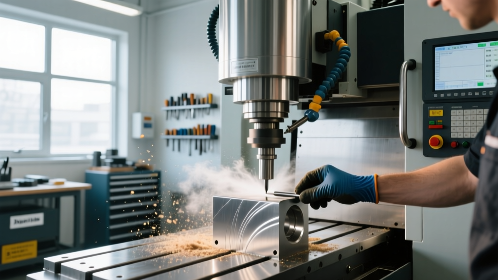
Optimizing a CNC machine center requires shifting focus from arbitrary spindle RPM limits to the fundamental physics of chip formation. The ultimate goal of parameter tuning is maximizing the Material Removal Rate (MRR) while maintaining tool life and surface finish integrity. MRR, measured in cubic inches per minute (CIM), is the true metric of machining efficiency.
At the core of MRR is the chip load, or Inches Per Tooth (IPT). This is the exact thickness of the material sheared away by a single cutting edge during one spindle revolution. If the IPT is too low, the cutting edge rubs instead of shearing, generating excessive heat and accelerating flank wear. If the IPT is too high, the cutting force exceeds the tool's transverse rupture strength, leading to micro-chipping or catastrophic fracture.
Core Optimization Formulas
RPM = (SFM × 3.82) / Tool Diameter
Feed Rate (IPM) = RPM × IPT × Number of Flutes
MRR (CIM) = Width of Cut (WOC) × Depth of Cut (DOC) × IPM
Spindle Speed (RPM) vs. Cutting Speed (SFM): Clearing the Confusion
A common error among novice programmers is treating the CNC machine center's maximum RPM as the target speed. Spindle speed (RPM) is merely a machine output; Cutting Speed (SFM - Surface Feet per Minute) is the material-dependent variable. SFM dictates the thermal and mechanical limits of the cutting zone.
For example, machining 6061-T6 aluminum requires an SFM of 1,000 to 1,500 to ensure the chip evacuates heat efficiently. Conversely, Ti-6Al-4V titanium demands an SFM of 90 to 130 to prevent the workpiece from work-hardening and welding to the carbide substrate. According to the Machining Doctor CNC Feeds and Speeds Calculator, ignoring SFM limits in favor of maxing out RPM on hard materials will destroy a $150 end mill in under three minutes.
Baseline Parameters for a Standard CAT40 VMC
The table below provides optimized starting parameters for a 1/2-inch (0.500"), 3-flute solid carbide end mill operating on a standard 10,000 RPM CAT40 spindle (e.g., Haas VF-2). These values assume a rigid setup with less than 0.001" of tool deflection.
| Material | Target SFM | Calculated RPM | IPT (Chip Load) | Feed Rate (IPM) |
|---|---|---|---|---|
| 6061-T6 Aluminum | 1,200 | 9,168 | 0.006" | 165.0 |
| 304 Stainless Steel | 250 | 1,910 | 0.002" | 11.4 |
| Ti-6Al-4V Titanium | 120 | 917 | 0.0015" | 4.1 |
Feed Rate Optimization and the Radial Chip Thinning Effect
When programming a CNC machine center for high-efficiency milling (HEM) or trochoidal toolpaths, the Width of Cut (WOC) or Radial Depth of Cut (RDOC) is often reduced to 5%–15% of the tool diameter. This introduces a geometric phenomenon known as radial chip thinning.
Because the tool enters the material at a shallow radial angle, the actual chip thickness becomes significantly thinner than the programmed IPT. If you maintain the standard feed rate, the effective chip load drops into the 'rubbing' zone, generating immense friction and heat. To compensate, the programmed feed rate must be multiplied.
⚠️ Critical Machining Warning: When RDOC is less than 50% of the tool diameter, failing to increase the feed rate to compensate for chip thinning will cause premature tool failure due to rubbing, particularly in abrasive materials like Inconel 718 or hardened tool steels.As outlined in the Sandvik Coromant milling knowledge base, the simplified multiplier for chip thinning can be estimated using the ratio of the tool diameter to the radial engagement. For a 1/2" end mill cutting at a 10% RDOC (0.050"), the effective chip thickness is roughly 30% of the programmed IPT. Therefore, the programmed feed rate must be increased by a factor of 3 to maintain the correct mechanical load on the cutting edge.
Real-World Troubleshooting: Diagnosing Suboptimal Parameters
Theoretical calculations only get you to the first cut. Real-world CNC machine center optimization requires reading the acoustic and visual feedback of the cut. Below is a diagnostic framework for common parameter failures.
- Symptom: High-pitch squealing or harmonic chatter during full-slotting.
Cause: The spindle RPM has excited the natural harmonic frequency of the tool-holder assembly.
Fix: Do not change the feed rate. Alter the RPM by exactly 12% to 15% (up or down) to break the harmonic resonance, or switch to a variable helix end mill to disrupt the harmonic wave. - Symptom: Stringy, welded chips on aluminum (Built-Up Edge / BUE).
Cause: SFM is too low, or the tool coating is chemically reactive with aluminum (e.g., TiAlN).
Fix: Increase SFM by 20% to raise the shear zone temperature above the BUE formation threshold, and switch to an uncoated, highly polished carbide end mill or one with a ZrN coating. - Symptom: Tapered walls in deep pocket milling (deflection).
Cause: Radial cutting forces are exceeding the tool's rigidity, pushing the cutter away from the programmed vector.
Fix: Reduce the IPT by 20% and increase the number of finishing passes, or utilize a tool with a shorter Length of Cut (LOC) to maximize the diameter-to-length ratio.
Advanced Controller Features for Dynamic Optimization
Modern CNC machine centers equipped with advanced controllers (such as the Fanuc 31i-B5 or Siemens Sinumerik 840D sl) possess 'look-ahead' capabilities that fundamentally alter how feed rates are executed. Look-ahead allows the controller to read hundreds of upcoming G-code blocks, anticipating sharp directional changes and decelerating the axes smoothly to prevent servo lag and corner overshoot.
When optimizing feed rates for complex 3D contouring, programmers must utilize the controller's dynamic feed tuning. According to Harvey Tool's technical support guidelines, relying solely on CAM-generated G-code without enabling the machine's High-Speed Machining (HSM) or Advanced Preview Control cycles will result in the machine physically pausing at every micro-node, destroying cycle times and leaving dwell marks on the part surface.
"A CNC machine center is only as fast as its block processing speed (BPS). If your controller processes at 1,000 blocks per second, but your CAM software outputs 5,000 micro-segments per inch for a smooth surface finish, your feed rate will bottleneck at the controller's math limit, not the spindle's torque limit."
By aligning the physical cutting parameters (SFM and IPT) with the digital capabilities of the machine's look-ahead buffer, manufacturers can safely push their CNC machine centers to the absolute limits of their mechanical rigidity, drastically reducing cycle times while extending tooling life.