CNC Machine 6 Axis Controller Training: Interfaces & Best Practices
Master CNC machine 6 axis controller interfaces. Expert training protocols, UI comparisons (Fanuc, Siemens), and TCP best practices for operators.
The Shift to 6-Axis: Why Controller UI Dictates Success
Transitioning a machine shop from standard 3-axis milling to a full CNC machine 6 axis configuration—typically a 5-axis simultaneous mill-turn center with an additional lower turret or robotic part handler—introduces exponential kinematic complexity. The bottleneck in this transition is rarely the mechanical rigidity of the machine; it is the operator's ability to intuitively navigate the Human-Machine Interface (HMI). In 2026, modern controllers process billions of calculations per second to maintain tool vectors, but if an operator cannot interpret the HMI's spatial feedback, the risk of a catastrophic collision remains high.
⚠️ CRITICAL WARNING: The 3-Axis to 6-Axis Transition TrapOperators trained exclusively on 3-axis VMCs often rely on the physical machine axes (X, Y, Z) moving linearly to the part. On a 6-axis mill-turn, a Z-axis command may result in the B-axis (spindle tilt) and C-axis (rotary table) moving simultaneously while the physical Z-slide remains stationary. Failure to understand this 'virtual axis' movement via the controller UI is the leading cause of $40,000+ spindle crashes during the first 90 days of 6-axis machine installation.
2026 Controller Ecosystem Matrix: Fanuc vs. Siemens vs. Heidenhain
When training operators, the foundational curriculum must be tailored to the specific controller ecosystem. The 'Big Three' dominate the 6-axis mill-turn and multi-tasking market, each with a radically different UI philosophy and Tool Center Point (TCP) management strategy.
| Controller Model | UI Paradigm | TCP Command | Avg. Training Time | Best Application |
|---|---|---|---|---|
| Fanuc 31i-B5 | Softkey / G-Code Modal | G43.4 / G43.5 | 40-50 Hours | High-volume aerospace production |
| Siemens SINUMERIK 840D sl (Operate) | Touch / Graphical Kinematics | TRAORI / TRACON | 30-40 Hours | Complex 3D contours & impellers |
| Heidenhain TNC 640 | Conversational (Klartext) | M128 | 25-35 Hours | Prototyping & Tool/Die shops |
Deep Dive: UI Navigation & TCP Management
On the Fanuc 31i-B5, operators must map the TCP softkeys to the primary screen. The G43.4 command (Tool Tip Center Point Control) forces the controller to calculate the inverse kinematics required to keep the tool tip exactly on the programmed XYZ coordinate, regardless of how the rotary B and C axes articulate. Training must emphasize that G43.4 is a modal state. If an operator manually jogs the machine in 'Handle' mode without canceling G43.4 via G49, the controller will attempt to maintain the tool vector relative to the part, causing unpredictable and violent rotary axis movements.
Conversely, the Siemens SINUMERIK 840D sl with the 'Operate' HMI abstracts much of the G-code via its graphical kinematic chain. Operators can visually see a 3D representation of the machine's pivot points on the touch screen. The Siemens equivalent, TRAORI (Transformation Orientation), is often engaged via a dedicated physical hardkey or a persistent on-screen toggle. Training here focuses less on memorizing G-codes and more on interpreting the 'Distance to Go' (DTG) readouts for the virtual rotary axes during simultaneous 5-axis contouring.
Step-by-Step Operator Training Protocol
To build muscle memory and spatial awareness, lead machinists should implement the following phased training framework for new 6-axis operators.
Phase 1: Kinematic Chain Visualization (Hours 1-10)
- Power On & Reference: Instruct the operator to home the machine and immediately navigate to the 'Position' screen. Have them manually jog the X-axis 10mm while the B-axis is tilted at 45 degrees. They must observe how the physical Z-slide and X-slide move in tandem to achieve the programmed X-vector.
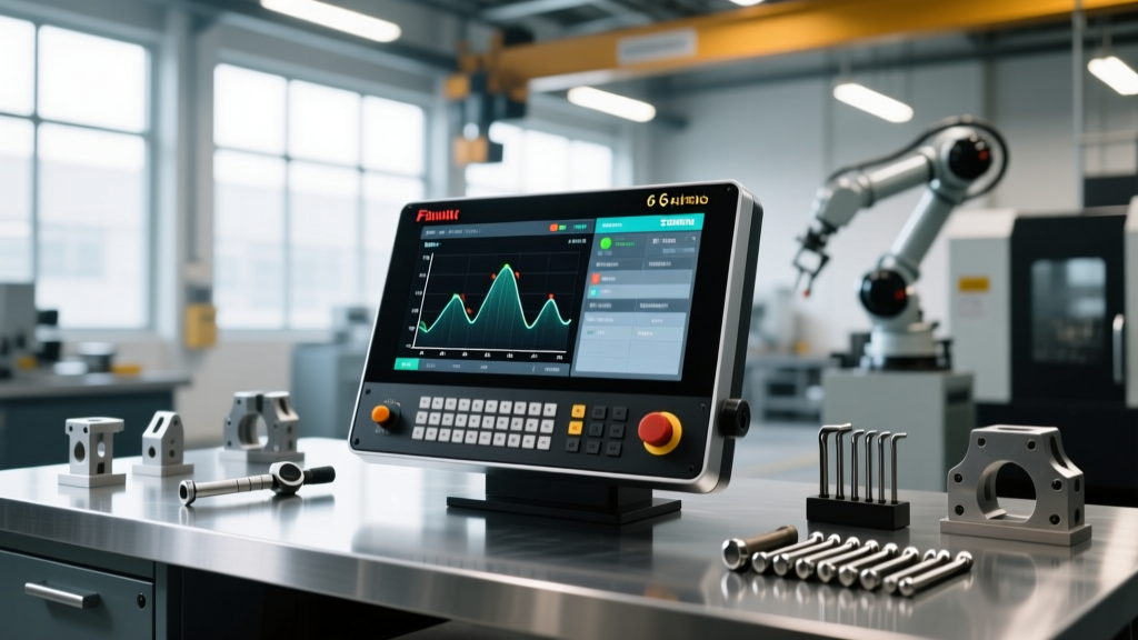
- DTG Monitoring: Teach operators to split the HMI screen. The primary pane should show standard absolute coordinates, while the secondary pane must display the rotary axis 'Distance to Go' and real-time vector angles.
Phase 2: Dry-Run Simulation & Single-Block Execution (Hours 11-25)
💡 PRO TIP: The 10% Rapid Override RuleDuring the first physical run of a 6-axis CAM program, operators must set the Rapid Override to 10% and engage Single-Block mode. On a Heidenhain TNC 640, utilize the 'Program Run with Graphic' feature to watch the toolpath simulation on the secondary monitor while the physical machine executes the block at reduced speed. This dual-verification prevents out-of-bounds rotary flips.
Phase 3: Work Offset Verification (Hours 26-40)
On a 6-axis mill-turn, setting the work offset (G54) is not just about touching off the X and Z diameters. Operators must be trained to use the controller's automated kinematic calibration cycles (such as Siemens' CYCLE996 or Fanuc's G68.2 tilted work plane probing). A 0.002-inch error in the Z-axis master tool length will force the B-axis to over-rotate by up to 3 degrees to maintain the surface normal, resulting in severe gouging on contoured aerospace blades.
Troubleshooting Common 6-Axis Interface Alarms
When a 6-axis machine faults, the HMI alarm screen provides the diagnostic roadmap. Operators must be trained to look beyond the primary alarm text and check the sub-diagnostic buffers.
- Fanuc Alarm PS0216 (Illegal axis command in TCP mode): This occurs when G43.4 is active, but the CAM post-processor outputs a standard 3-axis G01 move without defining the rotary axis vectors (I, J, K or A, B, C). Fix: The operator must manually insert a G49 (cancel TCP) before the 3-axis positioning move, then re-engage G43.4 for the subsequent contouring pass.
- Siemens Alarm 20092 (Axis travel limit exceeded during TRAORI): Often triggered when a workpiece zero offset is shifted slightly in Z. The controller calculates that to maintain the tool vector at the new Z-depth, the B-axis must flip 180 degrees, hitting the physical limit switch. Fix: Verify the Z-shift in the 'Workpiece Offsets' menu and run the 'Program Test' (dry run) graphical simulation to check for rotary axis singularities.
- Heidenhain Error 3004 (Axis not in manual mode for M128): Triggered when attempting to manually jog the rotary axes while Tool Center Point Management (M128) is active in the background. Fix: Press the 'Manual' hardkey, deactivate M128 via the softkey menu, jog to the safe position, and reactivate before returning to 'Program Run'.
Customizing the HMI for 6-Axis Workflows
A critical, yet frequently overlooked, best practice is HMI customization. Out-of-the-box controller interfaces are designed for general milling. For a dedicated 6-axis cell, the lead programmer should lock down the interface to prevent operator error.
'We reduced our 6-axis setup crashes by 40% simply by hiding the standard 3-axis softkeys on the Fanuc iHMI. If an operator doesn't need to manually input a G43.4 vector on the shop floor, that softkey shouldn't be on the screen. We pinned the 'Kinematic Status' and 'Rotary Axis Load' meters to the permanent header bar.' — Lead Manufacturing Engineer, Tier 1 Aerospace Supplier
On Siemens Operate, utilize the 'Easy Screen' configuration tool to create a custom '6-Axis Setup' dashboard. This dashboard should aggregate the B-axis and C-axis clamping status, the current TCP vector angles, and the lower-turret clearance proximity sensor data into a single, high-contrast view. By aligning the controller interface with the physical realities of 6-axis kinematics, shops can drastically reduce the learning curve, protect high-value spindles, and unlock the full cycle-time reduction potential of multi-tasking machinery.