Powering Smart CNC Machine Fixtures: 2026 Electrical Guide
Discover the 2026 electrical requirements, power setups, and PLC integration steps for upgrading to automated and smart CNC machine fixtures.
The Shift to Electro-Mechanical CNC Machine Fixtures
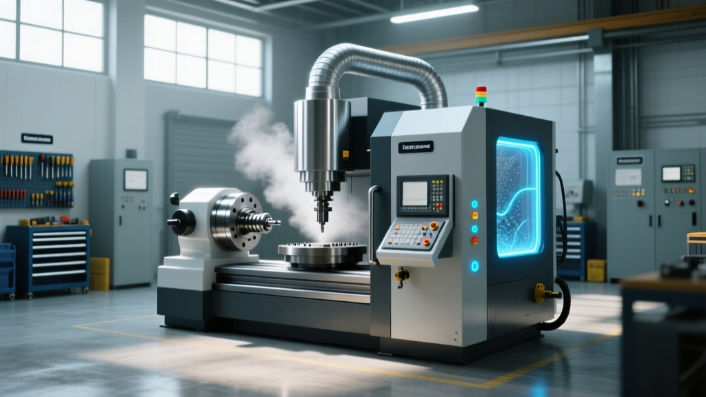
The transition from manual toggle clamps to automated, IoT-enabled CNC machine fixtures represents one of the most significant leaps in machining efficiency over the last decade. In 2026, modern fixturing systems utilize electromagnetic chucks, hydraulic clamps with electronic pressure transducers, and pneumatic solenoids embedded with RFID part-tracking sensors. While these smart CNC machine fixtures drastically reduce load/unload times and eliminate human clamping errors, they introduce complex electrical requirements that standard machine tool power setups are rarely equipped to handle out of the box.
Upgrading a 3-axis or 5-axis vertical machining center (VMC) to support advanced fixturing requires a dedicated evaluation of the machine’s electrical cabinet, control voltage availability, and M-code output mapping. Failing to properly isolate control circuits or underestimating the amperage draw of electromagnetic clamping can lead to severe voltage drops, PLC logic faults, and catastrophic workpiece ejection.
Core Power Requirements and Circuit Isolation
Traditional CNC machine electrical setups deliver 480V 3-phase power to the spindle and axis drives, stepping down to 110V AC for coolant pumps and 24V DC for control logic. Smart CNC machine fixtures often require a hybrid approach. Electromagnetic fixtures, such as those used for high-speed milling of ferrous metals, demand high-amperage DC rectification, while IoT sensor arrays require ultra-stable, isolated 24V DC to prevent signal noise.
⚠️ WARNING: Ground Loop HazardsNever share the 24V DC control ground of your CNC machine fixtures with the machine tool’s primary 24V logic ground. Electromagnetic chucks generate massive back-EMF (electromotive force) when deactivated. If not isolated via dedicated diode suppression modules, this voltage spike will travel through the shared ground, instantly frying the CNC controller’s I/O board. Always use a galvanically isolated DC-DC converter (e.g., Phoenix Contact MINI-PS-10-42AC/24DC/1) specifically for the fixturing circuit.
Voltage and Amperage Specifications
When specifying power supplies for automated CNC machine fixtures, calculate the total inrush current. A standard Roemheld hydraulic clamping manifold with electronic sequencing valves may draw only 2.5 amps continuously, but the inrush current when all solenoids fire simultaneously can spike to 14 amps for 40 milliseconds. Your 24V DC power supply must be rated for at least 20% above the peak inrush to prevent the CNC from triggering a low-voltage alarm mid-cycle.
Power Consumption Matrix: 2026 Fixture Technologies
Selecting the right fixture type dictates the electrical infrastructure required. The table below outlines the power profiles for the most common automated CNC machine fixtures utilized in high-mix, high-volume manufacturing environments today.
| Fixture Technology | Primary Voltage | Continuous Draw | Inrush Current | Required Infrastructure |
|---|---|---|---|---|
| Manual / Mechanical | N/A | 0A | 0A | None |
| Pneumatic (Solenoid) | 24V DC | 1.2A - 3A | 8A - 12A | Isolated 24V PSU, 14 AWG wiring |
| Hydraulic (Electronic Valve) | 24V DC / 110V AC | 2.5A - 5A | 14A - 20A | Dedicated 110V AC pump circuit, 24V DC control |
| Electromagnetic Chuck | 110V AC (Rectified) | 8A - 15A | 30A+ | Dedicated 20A 110V breaker, heavy-duty rectifier |
| IoT Smart Pallet System | 24V DC / PoE | 0.5A - 1.5A | 2A | Shielded CAT6, isolated 24V logic supply |
M-Code Mapping and PLC Relay Integration
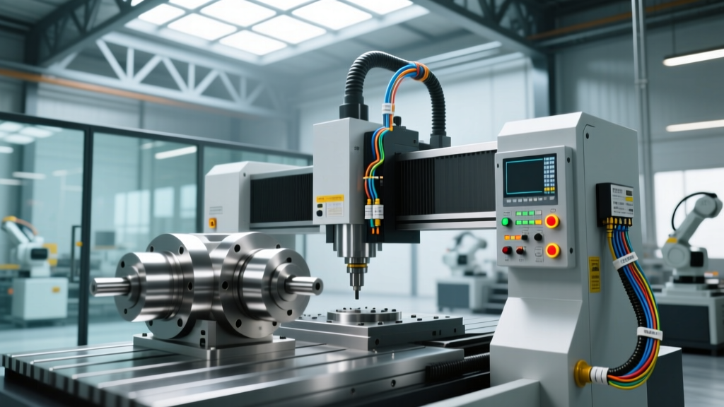
Automated CNC machine fixtures must be seamlessly integrated into the machine’s G-code program via M-codes. On standard Fanuc and Haas controllers, M10 and M11 are typically reserved for chuck open/close or clamp/unclamp functions. However, the controller’s internal I/O board cannot handle the amperage required to fire heavy hydraulic solenoids directly. You must use intermediary relays.
Step-by-Step Relay Wiring for Hydraulic Clamps
- Identify the Controller Output: Locate the M10/M11 output pins on the CNC’s I/O distribution block. These output a low-current 24V DC signal (usually under 300mA).
- Install Intermediary Relays: Mount DIN-rail relays (e.g., Phoenix Contact PLC-RSC- 24DC/21) inside the electrical cabinet. Wire the CNC’s M10 output to the relay coil’s A1 terminal, and A2 to the 0V DC common.
- Wire the Load Circuit: Run a dedicated 10 AWG wire from a 10A circuit breaker to the relay’s normally open (NO) contact (terminal 14). Connect the output (terminal 12) directly to the hydraulic fixture’s solenoid valve.
- Install Flyback Diodes: Solder a 1N4007 flyback diode across the solenoid coil terminals, with the cathode (striped end) facing the positive voltage. This absorbs the inductive kickback when the M11 unclamp command breaks the circuit, protecting your relay contacts from arcing and pitting.
- Map the Macro Variables: In the CNC parameters, ensure the M-code dwell time is set to at least 1.5 seconds. This allows the hydraulic pressure to reach the required 3,000 PSI and gives the electronic pressure transducer time to verify the clamping force before the spindle begins rotation.
Mitigating VFD Interference in Sensor Lines
A major challenge in 2026 smart manufacturing environments is electromagnetic interference (EMI). Modern CNC machines utilize Variable Frequency Drives (VFDs) for coolant pumps and chip conveyors. VFDs generate high-frequency electrical noise that can induce false signals in the unshielded sensor cables of your CNC machine fixtures, causing the machine to falsely read that a part is unclamped and triggering an E-stop.
According to the NFPA 79 Electrical Standard for Industrial Machinery, control wiring must be physically separated from power wiring. When routing fixture sensor cables, maintain a minimum 12-inch clearance from any VFD output cables. If crossing is unavoidable, the cables must intersect at a strict 90-degree angle. Furthermore, all fixture proximity sensors must utilize Shielded Twisted Pair (STP) cabling, with the shield grounded at the cabinet end only to prevent ground loops.
"The most common cause of phantom E-stops in automated pallet systems isn't a mechanical failure; it's VFD noise corrupting the 24V clamp-verification signal. Upgrading to shielded M12 sensor connectors and optical isolation relays eliminates 99% of these ghost faults."
— Lead Automation Engineer, Advanced Machining Solutions
Safety Interlocks and E-Stop Integration
Integrating automated CNC machine fixtures requires strict adherence to safety protocols. Under OSHA 1910.212 General Requirements for All Machines, any automated clamping system must be integrated into the machine’s safety chain. If a fixture loses hydraulic pressure or electrical continuity, the spindle must immediately halt.
Do not wire pressure switches directly into standard PLC inputs. Instead, use a dedicated safety relay module (such as a Pilz PNOZ s30). Wire the fixture’s electronic pressure transducer and the physical clamp limit switches in series through the safety relay. If the pressure drops below 2,500 PSI during a heavy roughing pass, the safety relay will instantly drop the main contactor, cutting power to the spindle drive and engaging the dynamic braking resistors, preventing the workpiece from becoming a lethal projectile.
2026 Retrofit Cost Analysis
Upgrading an existing VMC to handle smart CNC machine fixtures is a capital investment that yields rapid ROI through lights-out manufacturing capabilities. Below is a realistic cost breakdown for retrofitting a standard 40-taper VMC with a fully automated, hydraulically actuated tombstone fixture system, including all necessary electrical cabinet upgrades.
- Isolated 24V DC Power Supply & Breakers: $450 - $600
- Safety Relay Module (Pilz/Sick) & Wiring: $850 - $1,200
- Intermediary DIN Relays & Flyback Suppression: $300 - $450
- Shielded Sensor Cabling & M12 Bulkheads: $600 - $900
- Electrical Labor & PLC Mapping (20 hours @ $125/hr): $2,500
- Total Electrical Retrofit Cost: $4,700 - $5,650
While the electrical setup requires precision and adherence to industrial standards, the resulting capability to run untended machining shifts makes the integration of advanced CNC machine fixtures an indispensable upgrade for competitive machine shops. For further reading on advanced workholding mechanics, refer to the engineering data provided by Schunk Clamping Technology to ensure your mechanical specifications align with your electrical capabilities.