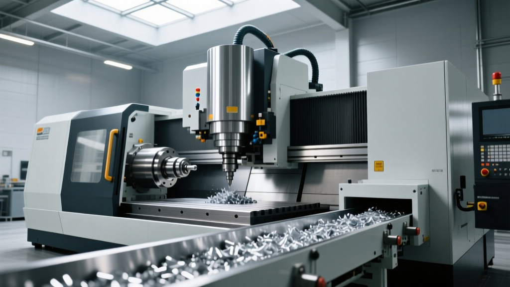
3-Axis Setup Guide: Training Operators on Top CNC Machine Brands
Master 3-axis CNC machine setup and capabilities. A training guide for operators covering top CNC machine brands, workholding, and control nuances.
The 3-axis vertical machining center (VMC) remains the workhorse of modern subtractive manufacturing. However, assuming all 3-axis mills operate identically is a critical training failure. When operators transition between top CNC machine brands, they encounter distinct control architectures, spindle thermal behaviors, and workholding compatibility requirements. In 2026, standard 3-axis VMCs routinely feature 12,000 to 15,000 RPM direct-drive spindles and 1,000+ IPM rapid traverse rates, meaning setup errors result in catastrophic crashes within milliseconds.
Operator Baseline: Before touching the control pendant, trainees must understand that a 3-axis machine's physical limits (work envelope, spindle taper, and Z-axis clearance) are fixed, but its effective capabilities are dictated entirely by the operator's setup methodology.Core 3-Axis Capabilities: What Operators Must Master
A 3-axis CNC mill moves the cutting tool along the X (left-right), Y (front-back), and Z (up-down) axes while the workpiece remains stationary on the table. The primary capability constraint is that the tool can only approach the workpiece from directly above. This necessitates multiple setups for complex geometries, increasing cumulative tolerance stack-up.
Top CNC machine brands engineer their 3-axis platforms with specific rigidity profiles. For example, the Haas VF-2SS utilizes a cast-iron frame optimized for high-speed aluminum and mild steel milling, offering a 40" x 20" x 20" travel envelope. Conversely, the Mazak VCN-530C features a heavier, more rigid casting designed to absorb the harmonic vibrations of hard-metal machining, albeit with a slightly smaller 41.3" x 20.8" x 20" work zone. Operators must match their cutting parameters (feed, speed, depth of cut) to the specific mass and damping characteristics of the brand they are operating.
Brand-Specific Control Nuances
The physical machine is only half the equation. The CNC control dictates setup speed and workflow. Below is a comparison of the dominant control ecosystems found across major CNC machine brands:
| Control System | Primary Brand Association | Setup Workflow Characteristic | Probe Integration |
|---|---|---|---|
| Haas NGC | Haas Automation | Highly intuitive, menu-driven WCS setting; excellent for fast job changeovers. | Native Visual Quick Code (VQC) for Renishaw probes. |
| Fanuc 0i-F Plus | DMG MORI, Doosan, Kitamura | Strict G-code reliance; steeper learning curve but unmatched macro flexibility. | Requires custom macro programming (G65) for automated probing. |
| Mazatrol SmoothG | Mazak | Conversational-first interface; allows complex 3D setups without CAM-generated G-code. | Seamless Renishaw integration via dedicated Mazak probing cycles. |
| Siemens 840D sl | DMG MORI, Hermle | ShopMill conversational GUI; powerful 3D simulation before cycle start. | Advanced cycle-based probing with graphical toolpath verification. |
Step-by-Step 3-Axis Setup Protocol for Trainees
A standardized setup protocol prevents crashes and ensures first-part success. Trainees must execute the following sequence regardless of the CNC machine brand, adapting only to the specific control interface.
- Machine Homing & Thermal Warm-Up
- Execute the Z-axis return-to-home (G28 Z0) first to prevent tool collisions with fixtures.
- Run a 10-minute spindle warm-up program. Critical Data: A cold 12,000 RPM spindle can exhibit up to 0.0015" of thermal growth in the Z-axis during the first hour. Warming it to 3,000 RPM stabilizes the bearing preload.
- Work Coordinate System (WCS) Establishment
- Mount the workpiece and indicate the primary datum within 0.0005".
- Use a Renishaw OMP60 spindle probe (or a calibrated edge finder) to set G54 X and Y. Never rely on manual paper-feel methods for production setups.
- Tool Length Offset (TLO) Measurement
- Use the machine's automatic tool setter (e.g., Haas TS300 or Mazak tool eye).
- Verify the TLO by manually touching off a 1.000" gage block on the Z-datum. If the control reads Z1.0005", apply a -0.0005" wear offset to the tool page.
- Dry Run & Graphical Verification
- Run the program with Z-axis shift elevated by 2.0" and rapid override set to 25%.
- Monitor the control's toolpath simulation to ensure retract heights (G98 vs G99) clear the highest point of the workholding.
Workholding & Tooling: Matching Brand Rigidity to Setup
The capability of a 3-axis mill is bottlenecked by its workholding. Operators must understand clamping forces and toolholder retention.
For standard vise work, the Kurt DX6 remains the industry standard, delivering 4,960 lbs of clamping force at 90 lbs of handle torque (costing approximately $1,450 in 2026). However, when operating high-torque 50-taper machines like the Okuma MB-46V, operators should upgrade to hydraulic vises or utilize direct toe-clamping to fully exploit the machine's heavy-duty roughing capabilities.
Toolholding is equally critical. Top CNC machine brands utilize different spindle tapers to manage pull-out forces:
- CAT40 (V-Flange): Standard on most American brands (Haas, Hurco). Excellent for high-speed machining but prone to Z-axis growth at extreme RPMs due to flange expansion.
- BT40 (MAS 403): Standard on Japanese brands (Mazak, Makino). Symmetrical flange design provides superior radial balance and accuracy at 15,000+ RPM.
- HSK-A63: Face-and-taper contact. Mandatory for 3-axis hard milling where Z-axis rigidity cannot be compromised.
"An operator who applies CAT40 high-speed parameters to a BT40 spindle, or vice versa, is ignoring the fundamental mechanical design of the machine brand they are running. Tool retention knobs must be matched exactly to the spindle's pull-stud retention angle—mixing 45-degree and 90-degree pull studs will result in the tool ejecting at 10,000 RPM." — Lead Manufacturing Engineer, Tier 1 Aerospace Supplier
Troubleshooting Common 3-Axis Setup Failures
When a 3-axis setup fails, operators must systematically isolate the variable. Use this diagnostic framework:
Symptom: Severe Chatter During Finishing Passes
- Cause 1: Tool overhang exceeds 4x diameter. Fix: Switch to a stub-length endmill or use a shrink-fit holder (e.g., Haimer) to maximize Z-clearance and rigidity.
- Cause 2: Workpiece resonance. Fix: Add a sacrificial dampening block or switch from climb milling to conventional milling for the final 0.005" of stock removal.
Symptom: Z-Depth Inconsistency Across the Table
- Cause 1: Table tram error. Fix: Sweep the table with a 0.0001" indicator. If out of tolerance by more than 0.0005" over 12 inches, the machine requires mechanical realignment.
- Cause 2: Thermal expansion of the spindle housing. Fix: Implement a mandatory 15-minute spindle warm-up cycle and re-touch off the Z-datum before running critical tolerance features.
Certification Standards and Continuous Training
Shop floor proficiency should be validated against recognized industry benchmarks. According to training frameworks established by the National Institute for Metalworking Skills (NIMS), operators must demonstrate competency in blueprint reading, GD&T interpretation, and precise WCS establishment before operating 3-axis VMCs independently.
Furthermore, resources from the Society of Manufacturing Engineers (SME) emphasize that cross-training operators on multiple CNC machine brands reduces shop-floor bottlenecks. An operator fluent in both Haas NGC conversational workflows and Mazak SmoothG logic can seamlessly transition between prototype and production cells, maximizing overall equipment effectiveness (OEE) and minimizing setup-related scrap.