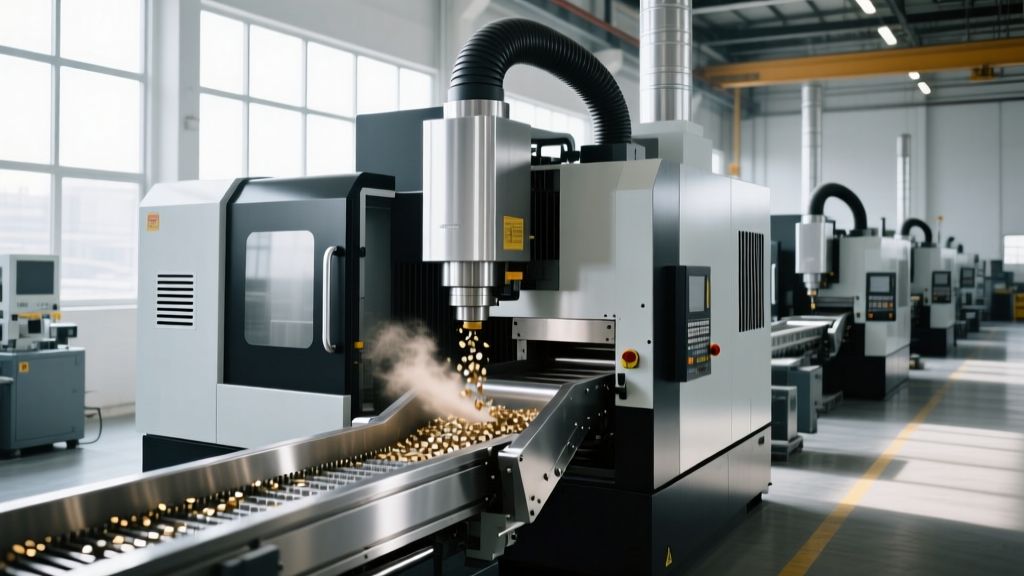
Operator Training: Using CNC Machine Monitoring for 3-Axis Setup
Train operators to maximize 3-axis CNC capabilities using real-time CNC machine monitoring. Master setup best practices, sensor calibration, and telemetry.
The Shift from Intuition to Data-Driven 3-Axis Setup
Three-axis vertical machining centers (VMCs) like the Haas VF-2SS or the DMG MORI M1 remain the undisputed workhorses of modern job shops. Historically, setting up a 3-axis mill for a new production run relied heavily on operator intuition—listening to the cutting forces, watching the chip color, and manually tweaking the feed rate override dial. While experienced machinists can achieve great results this way, it is inherently unscalable and prone to human error.
Integrating cnc machine monitoring into the initial setup phase transforms this subjective process into a precise, repeatable science. By equipping operators with real-time telemetry during the first-article run, shops can lock in optimal feeds, speeds, and depth-of-cut (DOC) parameters based on empirical data rather than guesswork. According to the NIST Smart Manufacturing guidelines, data-driven setup protocols reduce first-article scrap rates by up to 22% and extend tool life by establishing verified baseline load limits.
Core Capability Shift: A standard 3-axis mill is limited by its static G-code programming. When augmented with real-time monitoring, the machine's effective capability expands to include dynamic chatter avoidance, predictive tool wear tracking, and automated spindle load balancing.Hardware Selection: Equipping the 3-Axis Mill for Telemetry
Before operators can be trained to interpret data, the machine must be properly instrumented. Modern 3-axis setups require a combination of internal controller data (via MTConnect adapters) and external physical sensors. The MTConnect Institute standard remains the foundational protocol for extracting internal PLC data from controllers like the Fanuc 0i-F Plus or Siemens Sinumerik 840D.
| Sensor Type | Parameter Measured | Typical 2026 Cost | Installation Point & Sampling Rate |
|---|---|---|---|
| Spindle Load (Internal) | Motor torque percentage | $0 (via MTConnect) | Controller PLC / 50-100 Hz |
| Triaxial Accelerometer | Vibration & chatter harmonics | $450 - $850 | Spindle housing / 10 kHz+ |
| Acoustic Emission (AE) | High-frequency stress waves | $1,200 - $2,500 | Tool holder or spindle nose / 100 kHz |
| Power Analyzer | 3-phase power consumption | $300 - $600 | Main electrical panel / 1 kHz |
Step-by-Step Operator Training: Establishing the Baseline Cut
Operator training must focus on the Baseline-Deviate-Correct (BDC) framework. The goal during a 3-axis setup is not to run the machine at maximum capacity immediately, but to establish a verified baseline that the monitoring software can use to detect anomalies during lights-out or high-volume production.
- Initialize Single-Block and Dry Run: Operators must first run the toolpath in single-block mode with the Z-axis shifted +2.0 inches to verify rapid traverse paths and ensure no fixture collisions occur before cutting forces are introduced.
- Engage 50% Feed Override for First Engagement: When the tool (e.g., a 1/2-inch 3-flute carbide endmill) first contacts the raw material, the feed override should be set to 50%. This prevents shock-loading the spindle and provides a clean, low-noise baseline for the vibration sensors.
- Ramp to 100% and Record the Baseline: Gradually increase the feed override to 100% over three successive passes. The operator must record the steady-state spindle load percentage and the RMS vibration value. For roughing 6061-T6 aluminum, a healthy baseline spindle load is typically between 35% and 55%.
- Establish the Alarm Thresholds: Operators are trained to set the upper alarm limit at exactly 20% above the recorded baseline. If the baseline load is 45%, the alarm triggers at 65%. This accounts for normal material hardness variations without triggering false positives.
- Verify Chip Evacuation Telemetry: In 3-axis milling, deep pocketing often leads to chip recutting. Operators must watch for micro-spikes in the acoustic emission (AE) sensor data, which indicate chips being dragged across the machined surface, prompting a reduction in DOC or an increase in spindle RPM to improve chip thinning.
Translating Telemetry into Setup Adjustments
Data is useless if the operator does not know how to adjust the 3-axis setup in response to it. Training must bridge the gap between screen readouts and physical machine adjustments.
Spindle Load Variance and Tool Deflection
If the CNC machine monitoring dashboard shows a steady increase in spindle load over the first five parts of a setup run, the operator is witnessing tool wear. However, if the load spikes erratically within a single toolpath, it indicates tool deflection or an inconsistent workpiece surface.
Action: For erratic spikes on long-reach 3-axis tools, reduce the radial engagement (stepover) by 15% while maintaining the axial depth of cut, which drastically reduces lateral cutting forces without sacrificing material removal rates (MRR).
Vibration Harmonics and Chatter Detection
Chatter in 3-axis milling often occurs when the spindle RPM aligns with the natural frequency of the tool-holder-workpiece system. External accelerometers sampling at 10 kHz will display a distinct frequency spike on a Fast Fourier Transform (FFT) graph.
Action: Train operators to use the 'Tap Test' feature on modern monitoring tablets. By adjusting the spindle speed up or down by 5-8% based on the stability lobe diagram generated by the software, operators can move the cutting frequency out of the chatter zone, saving the surface finish and preventing carbide micro-chipping.
Real-World Scenario: Optimizing Aluminum 6061 Roughing Passes
Consider a setup on a Doosan DNM 4500 3-axis mill utilizing a Kennametal HARVI III 1/2-inch endmill for roughing aerospace brackets out of 6061-T6 aluminum. The programmed parameters are 12,000 RPM, 150 IPM feed rate, and a 0.2-inch DOC.
During the first-article run, the operator observes the CNC machine monitoring dashboard. The spindle load holds steady at 42%, but the triaxial accelerometer detects a 4.5g RMS vibration spike every time the tool enters a corner. The corner entry increases the radial engagement from 50% (slotting) to over 110% (cornering), causing a momentary shock load.
The Setup Adjustment: Instead of globally reducing the feed rate—which would ruin the cycle time—the trained operator edits the CAM post-processor to include a 40% feed reduction strictly for cornering moves (using G1 F-codes localized to the corner radii) and adds a 0.05-inch helical ramp entry. The subsequent monitored run shows vibration dropping to a stable 1.2g RMS, and the spindle load normalizes, proving the setup is ready for high-volume production.
FAQ: Common Operator Questions on Monitoring Integration
How do we handle sensor drift during long 3-axis production runs?
Accelerometers mounted on the spindle housing can experience thermal drift as the machine warms up. Operators should be trained to perform a 10-second 'idle baseline' capture every morning after the spindle has completed its standard warm-up cycle (typically 15 minutes at 8,000 RPM). This recalibrates the zero-point for the vibration sensors.
Can CNC machine monitoring detect workholding failures on a 3-axis mill?
Yes. If a part shifts slightly in a standard Kurt DX6 vise, the cutting forces will change asymmetrically. Power analyzers monitoring the X and Y axis servo motors will detect an imbalance in current draw between the axes. A sudden 15% spike in the Y-axis servo current during an X-axis contour move is a primary indicator of workholding slip.
What is the ROI timeline for retrofitting older 3-axis VMCs with monitoring hardware?
For a standard $4,500 hardware and edge-computing software retrofit per machine, shops typically see ROI within 4 to 6 months. This is achieved through a 20% reduction in scrap from first-article setup errors and a 30% decrease in premature tool changes driven by verified, data-backed tool life limits rather than conservative time-based estimates.