3-Axis CNC Machining Setup: Capabilities & Operator Best Practices
Master 3-axis CNC machining setup with our operator guide. Explore capabilities, workholding best practices, and troubleshooting tips for precision parts.
Core Capabilities and Kinematic Limits of 3-Axis CNC Machining
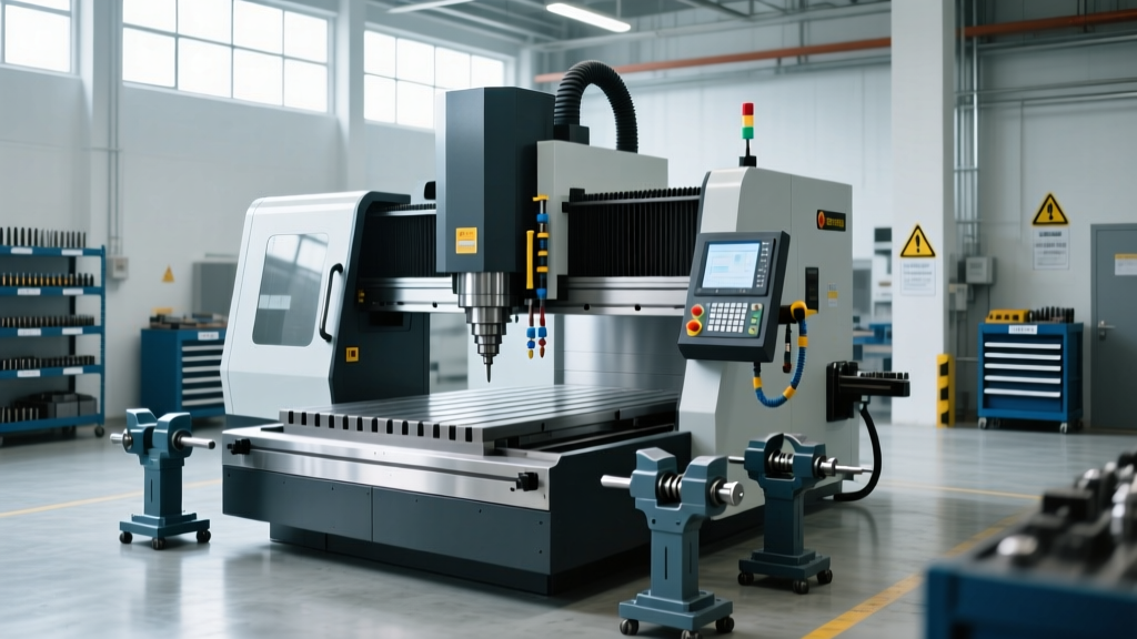
3-axis CNC machining remains the backbone of modern subtractive manufacturing. In a standard Vertical Machining Center (VMC), the cutting tool moves along the X (left-right), Y (front-back), and Z (up-down) linear axes, while the workpiece remains stationary on the machine table. This configuration excels at prismatic parts, enclosures, brackets, and 2.5D geometries.
However, understanding the kinematic limitations is critical for operators. Unlike 4-axis or 5-axis CNC machining, a 3-axis machine can only access the top face of a part in a single setup. Features on secondary planes require manual or automated re-fixturing, which introduces cumulative tolerance stack-up. Furthermore, deep cavity milling is constrained by the tool's length-to-diameter (L/D) ratio; exceeding a 5:1 L/D ratio with standard carbide endmills inevitably leads to deflection, chatter, and premature tool failure.
💡 Operator Insight: When programming deep pockets on a 3-axis VMC, utilize trochoidal milling toolpaths. This maintains a constant radial engagement angle, allowing you to use shorter, more rigid tools while achieving greater axial depths of cut (ADOC) without exceeding the machine's spindle torque limits.2026 Market Benchmark: Top 3-Axis VMCs
Selecting the right machine requires matching the working envelope and spindle characteristics to your part geometry and material. Below is a comparison of three industry-standard 3-axis VMCs dominating job shops and production floors in 2026.
| Machine Model | Spindle Taper / RPM | Work Envelope (X, Y, Z) | Rapid Traverse Rates | Est. Base Price (2026) |
|---|---|---|---|---|
| Haas VF-2SS | 40-Taper / 12,000 RPM | 30' x 20' x 20' | 1,400 ipm | $74,500 |
| DMG MORI CMX 600V | SK40 / 12,000 RPM | 23.6' x 22' x 20' | 1,181 ipm | $89,000 |
| Brother S500Z1 | BT30 / 16,000 RPM | 19.7' x 15.7' x 11.8' | 1,968 ipm | $68,000 |
Operator Setup: Workholding and Vise Indicating
Precision CNC machining is impossible without rigid, repeatable workholding. The standard 6-inch CNC vise (such as the Kurt DX6) is the workhorse of the 3-axis VMC. Improper setup here is the leading cause of out-of-tolerance parts. Follow this exact procedure for indicating and securing a standard milling vise.
- Clean the Table and Vise Base: Use a dedicated machine cleaner or aerosol WD-40 to wipe down the T-slot table and the bottom of the vise. Even a 0.001-inch metal chip trapped under the vise will cause it to rock, ruining your Z-axis flatness.
- Position the T-Nuts and Clamps: Use 5/8'-11 T-nuts. Place the clamps directly over the vise mounting slots. Ensure the clamps are perfectly parallel to the table; if they angle upward, the clamping force will push the vise sideways rather than down.
- Indicate the Fixed Jaw: Mount a 0.0005-inch resolution dial test indicator on the spindle. Sweep the indicator across the fixed jaw. Use a polyurethane dead-blow mallet (never a steel hammer) to tap the vise into alignment until the indicator reads zero variation across the entire jaw travel.
- Apply Final Torque: Once aligned, torque the hold-down bolts to 80-100 ft-lbs using a calibrated torque wrench. Hand-tightening is insufficient for heavy roughing operations and will allow the vise to lift during aggressive Z-axis cuts.
- Seat the Part: Place the raw material on precision ground parallels. Strike the top of the material with a soft lead or copper mallet until the parallels are 'locked' and cannot be moved by hand. This ensures the part is fully seated against the parallels before the vise is fully tightened.
Toolholding Strategies and Runout Management
The connection between the spindle and the cutting tool dictates surface finish and tool life. While ER collets are versatile, they introduce runout that compounds at the tool tip.
Tooling Rule of Thumb: For finishing operations and high-speed machining (HSM) exceeding 8,000 RPM, abandon ER collets. Switch to shrink-fit toolholders (like those from HAIMER or Zoller). Shrink-fit holders guarantee a concentricity of less than 3 microns (0.00012 inches) at 3xD projection, drastically reducing chatter and extending endmill life by up to 40% compared to standard collet chucks.
For roughing operations where cutting forces are high but surface finish is secondary, hydraulic chucks or heavy-duty milling chucks provide the necessary radial rigidity to absorb the shock loads of interrupted cuts. Always clean the spindle taper and the toolholder V-flange with a lint-free cloth and isopropyl alcohol before every tool change to prevent micro-welding and taper fretting.
Troubleshooting Setup-Induced Tolerancing Errors
When a 3-axis CNC machined part fails inspection, the root cause is frequently traced back to the physical setup rather than the CAM programming. Use this decision matrix to diagnose and correct common setup errors.
| Symptom on Part | Probable Root Cause | Corrective Action |
|---|---|---|
| Taper on vertical Z-axis walls | Vise jaw lifting under clamping load; part pushed up during tightening. | Use step-clamps or apply downward force with a dead-blow hammer while taking up the final vise tension. Ensure parallels are clean. |
| Severe chatter on long endmills | Tool stickout exceeds 4xD in a standard ER collet; harmonic resonance. | Switch to a shrink-fit holder, reduce stickout to the absolute minimum, or utilize variable-pitch endmills to break harmonics. |
| Out-of-flatness on top face | Material bowed upward when vise was tightened; relaxed when unclamped. | Use soft jaws machined to the exact contour of the part, or switch to a vacuum fixture / double-sided tape for thin-walled components. |
| Holes drilled off-center | Work Coordinate System (WCS) established on a burr or unmachined edge. | Always probe or edge-find a pre-machined, clean datum surface. Never trust a raw saw-cut edge for WCS establishment. |
Advanced Probing and WCS Establishment
Manual edge finding with a 0.200-inch electronic edge finder is a legacy practice that introduces human error and consumes valuable spindle time. Modern 3-axis CNC machining relies on spindle-mounted touch probes, such as the Renishaw OMP60, to automate Work Coordinate System (WCS) establishment and in-cycle part inspection.
Operators must understand the specific macro variables and G-codes required to deploy these probes safely. For example, probing a single vertical surface to set the X-axis zero typically utilizes a macro call like G65 P9811 X0 D1.0 (depending on the control and probe manufacturer). This command moves the probe to the surface, triggers the stylus, and automatically updates the G54 X-axis offset.
When probing internal bores, utilize a 4-point bore probing cycle (e.g., G65 P9832). This not only establishes the X and Y center of the bore but also calculates the actual diameter, allowing the control to flag a 'Part Out of Tolerance' alarm if the bore was rough-machined undersize before the finishing pass. Integrating automated probing into your 3-axis setup reduces load-to-load setup times by up to 85% and eliminates the scrap generated by manual data-entry errors into the machine control.
For comprehensive toolpath strategies and cutting data optimization across various materials, operators should regularly consult the Sandvik Coromant Milling Knowledge Base, which provides up-to-date feed and speed calculations, tool deflection formulas, and insert geometry selections specific to 3-axis VMC kinematics.