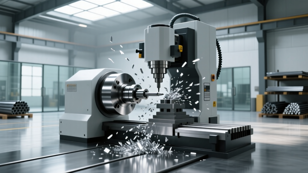
Mastering 3-Axis CNC Machine Setup: Operator Best Practices
Master 3-axis CNC machine setup with expert operator training guidelines. Learn workholding, tool calibration, and G-code verification best practices.
A poorly executed 3-axis CNC machine setup does not merely scrap a $500 titanium billet; it risks an $18,000 spindle cartridge replacement and weeks of downtime. For operators transitioning from manual machining, or veteran CNC machinists refining their workflow, mastering the 3-axis setup sequence is the dividing line between profitable production and catastrophic failure. This guide details the exact mechanical, thermal, and programmatic protocols required to set up a 3-axis vertical machining center (VMC) with zero-defect precision.
CRITICAL SAFETY & COST WARNING: According to OSHA standard 1910.212, all machine guarding must be in place during operation. However, during setup, operators frequently bypass interlocks to indicate vises. Always use Single Block mode and keep your hand on the Feed Hold button when verifying Z-axis clearances. A 100% rapid G00 crash into a hardened steel vise jaw will instantly shatter a $450 carbide end mill and compromise the spindle taper.Thermal Stabilization and Geometry Verification
Cast iron and Meehanite machine structures expand asymmetrically as they reach operating temperature. A cold Haas VF-2, for example, can experience up to 0.0015 inches of Z-axis thermal growth in the first 45 minutes of heavy milling. If you set your Z-axis work offset on a cold machine, your first part will be undersized in the Z-axis, and subsequent parts will gradually shift as the spindle bearings and ballscrews heat up.
The 15-Minute Warm-Up Protocol
Before indicating the vise or loading tools, execute a standardized warm-up program. As of 2026, modern controls like the Haas NGC and Fanuc 0i-F Plus feature built-in thermal compensation, but physical stabilization remains mandatory.
- Spindle: Ramp from 500 RPM to 8,000 RPM in 1,000 RPM increments, holding each speed for 60 seconds.
- Axes: Command the X, Y, and Z axes to travel to 80% of their maximum stroke limits using G01 at 100 IPM, then return to center. This distributes the way lube and stabilizes the ballscrew temperature.
- Verification: After the warm-up, sweep the machine table with a 0.0005-inch resolution test indicator to verify the table is within 0.0002 inches of flatness relative to the spindle.
Workholding Mechanics and Clamping Forces
The most common 3-axis CNC machine setup failure occurs at the workholding stage. Operators often rely on brute force rather than mechanical advantage. When using a standard 6-inch precision vise like the Kurt DX6, the angular lock mechanism is designed to pull the movable jaw down and forward, eliminating jaw lift.
OPERATOR TIP: Never use a cheater bar or extension pipe on the vise handle. Applying excessive leverage generates upwards of 12,000 lbs of clamping force, which will physically bow the vise base off the T-slots and distort your part. Use a standard handle and torque to approximately 60 ft-lbs (yielding ~4,500 lbs of clamping force). Always strike the top of the part with a 1.5 lb polyurethane deadblow mallet to seat it firmly against the parallels before final tightening.For high-volume 3-axis production, Sandvik Coromant's machining fundamentals emphasize matching clamping force to cutting forces to prevent part deflection without over-stressing the material.
| Workholding Method | Best Application | Max Recommended Clamping Force | Operator Edge Case / Gotcha |
|---|---|---|---|
| Kurt DX6 Standard Vise | Prismatic parts, die blocks, fixtures | 4,500 lbs (60 ft-lbs) | Hydraulic fluid on parallels causes micro-slippage during heavy roughing. |
| 6061 Aluminum Soft Jaws | Complex contours, fragile castings, 2nd ops | 1,500 lbs (25 ft-lbs) | Failing to leave a 'pip' or button at the back of the jaw during boring ruins Z-depth repeatability. |
| Low-Profile Toe Clamps | Large plates, 5-sided machining on 3-axis | 8,000 lbs (per clamp) | Clamp step-down must be precisely matched to part height to avoid Z-axis interference. |
Tool Length and Work Offset Calibration
Accurate work offsets (G54-G59) and tool length compensation (G43) are the mathematical foundation of the 3-axis CNC machine. A 0.001-inch error here cascades through every tool change in the program.
X and Y Axis Work Offsets (G54)
While mechanical edge finders (0.200-inch tip diameter) are reliable, they require the operator to visually interpret the 'kick' of the tip, introducing human error. For setups requiring tolerances tighter than ±0.001 inches, use a electronic 3D sensor like the Haimer 3D Sensor or a Renishaw OMP60 spindle probe. When using a mechanical edge finder, always approach the part from the same direction to account for axis backlash, and remember to subtract the 0.100-inch radius from your final machine coordinate.
Z-Axis Tool Length Offsets (G43 H_)
Never use the 'paper feel' method for Z-axis tool setting in a production environment. Use a dedicated Z-axis setter (typically 2.000 inches or 4.000 inches high) or a tool setting arm.
- Home the machine (G28 Z0).
- Place the Z-axis setter on the part surface (ensure the surface is clean of chips).
- Jog the tool down in 0.0001-inch increments until the gauge compresses to zero.
- Input the tool length geometry offset. If using a 2.000-inch setter, the control must account for the block height (e.g., Input Z2.0 or use the control's 'Tool Offset Measure' function with the block height pre-programmed).
Soft Jaw Machining and Coordinate Systems
When setting up a secondary operation on a 3-axis CNC machine, operators frequently machine custom soft jaws. The best practice is to bore the soft jaws in-situ (while mounted in the vise) to ensure perfect concentricity and parallelism to the spindle.
The 'Pip' Technique: When facing the soft jaws to create a Z-depth step, always leave a small uncut 'pip' or button at the very back of the jaw. This pip acts as a physical datum. If the jaws are ever removed and reinstalled, the operator can touch off the Z-axis on this exact pip, guaranteeing the Z-depth step is identical to the original setup. Assign the top of the vise jaws to G54, and the step inside the soft jaw to G55 to prevent coordinate confusion.
G-Code Verification and Dry Run Protocols
Running a new program in Memory (MEM) mode at 100% rapid override is the primary cause of setup crashes. As detailed in various Haas Automation Service Tips, verifying the tool path requires a disciplined, multi-layered approach.
'Distance-to-Go (DTG) is your ultimate safeguard. If the DTG to the Z-clearance plane reads 0.500 inches, but the tool tip is visibly 3.0 inches above the part, your Z-work offset is fundamentally incorrect. Stop the machine immediately.'
The First-Part Execution Sequence
- Rapid Override: Set G00 rapids to 5% or 25%.
- Single Block (SBK): Engage SBK to execute the program one line at a time.
- Optional Stop (M01): Ensure M01 is active at the end of every tool change to verify tool wear offsets and part dimensions before the next tool engages.
- Watch the Z-Axis Load Meter: During the initial plunge, if the spindle load spikes before the tool contacts the material, you have a Z-offset error or a missing G43 tool length command.
Common Setup Failure Modes and Troubleshooting Matrix
Even with rigorous protocols, 3-axis setups encounter edge cases. Use this decision matrix to diagnose and correct common setup anomalies without scrapping the part.
| Symptom / Anomaly | Root Cause Analysis | Corrective Action |
|---|---|---|
| Severe chatter during finishing pass | Tool stick-out exceeds 3x diameter; harmonic resonance. | Reduce stick-out; switch to a carbide stub-length end mill; apply variable helix tooling. |
| Part shifts in vise during roughing | Hydraulic fluid on parallels; insufficient clamping force on raw billet. | Clean parallels with isopropyl alcohol; machine serrated soft jaws for aggressive billet gripping. |
| Z-axis crashes into part on tool change | Missing G43 H_ (Tool Length Comp) in the tool change N-line block. | Verify tool change block includes G43 H_ Z1.0. Never separate G43 from the Z-axis clearance move. |
| Tool breaks on initial plunge | Plunge feed rate (F) too high for center-cutting end mill; or tool is not center-cutting. | Ramp into the material using G02/G03 helical interpolation instead of a direct Z-axis plunge. |
| Y-axis dimensional drift across batch | Thermal expansion of the Y-axis ballscrew pushing the table forward. | Implement a mid-batch thermal compensation offset update; ensure way lube is flowing to the Y-axis. |
Mastering the 3-axis CNC machine setup requires treating the machine as a dynamic system rather than a static tool. By controlling thermal variables, respecting clamping mechanics, and executing disciplined G-code verification, operators transform the VMC from a liability into a high-precision, high-yield manufacturing asset.