How CNC Machine Frame Rigidity Dictates 3-Axis Setup Limits
Master 3-axis CNC machine setup by optimizing your CNC machine frame rigidity. Learn best practices for leveling, damping, and maximizing milling accuracy.
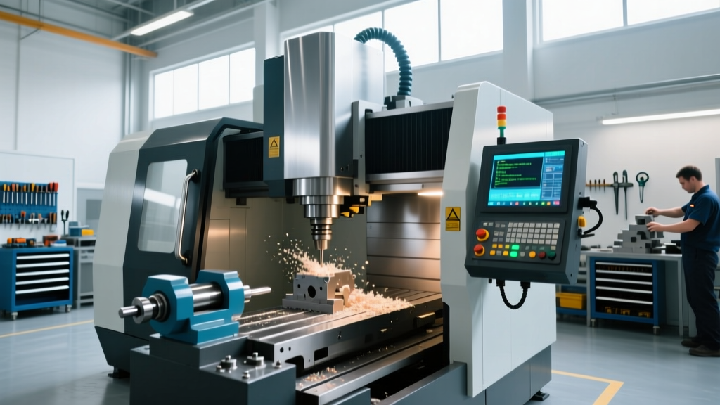
The maximum achievable accuracy and surface finish of a 3-axis vertical machining center (VMC) are rarely limited by the controller or the spindle bearings. In practice, the bottleneck is the CNC machine frame. A frame lacking sufficient mass, geometric stability, or damping capacity will amplify cutting forces into harmonic vibrations, destroying tool life and holding tolerances. Proper setup, isolation, and compensation protocols are required to extract the full capability from 3-axis platforms like the Haas VF-2SS or Doosan DVF 5000.
WARNING: Harmonic Resonance TrapsOperating a 3-axis mill at specific RPMs that match the natural frequency of an improperly isolated CNC machine frame will cause catastrophic chatter. This typically manifests between 6,000 and 9,000 RPM on lighter welded-steel frames. Always perform a tap-test or use an accelerometer to map your machine's stable speed zones before running high-radial-depth roughing cycles.
Material Science: Analyzing Frame Damping and Rigidity
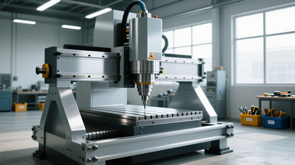
The foundational capability of any 3-axis setup begins with the base material. Machine tool builders select frame materials based on a trade-off between static rigidity (resistance to deflection under load) and dynamic damping (ability to absorb vibrational energy). Understanding your specific frame material dictates how aggressively you can push 3-axis cutting parameters.
| Frame Material | Damping Capacity | Thermal Expansion | Optimal 3-Axis Application |
|---|---|---|---|
| Welded Steel | Low (1x baseline) | High (~12 µm/m°C) | Light-duty routing, aluminum prototyping |
| Grade 40 Cast Iron | Medium (10x baseline) | Medium (~10.4 µm/m°C) | General 3-axis milling, steel/titanium roughing |
| Polymer Concrete (e.g., Epigranit) | High (60x baseline) | Very Low (~3 µm/m°C) | High-speed 3-axis finishing, micro-milling, mold making |
According to research published via the Society of Manufacturing Engineers (SME), polymer concrete bases reduce vibration amplitudes by up to 80% compared to traditional cast iron, allowing for significantly higher spindle speeds without inducing surface finish defects. However, polymer concrete lacks the tensile strength of iron, meaning the CNC machine frame must be heavily reinforced with steel anchors to handle the static tension of axis acceleration.
The 5-Step Precision Leveling Protocol
A twisted CNC machine frame induces geometric errors that compound as the Z-axis extends. If the base is not leveled to exacting standards, the linear guideways will bind, causing servo lag and circularity errors in 3-axis contouring. Do not rely on standard carpenter levels; the setup requires a master precision level with a resolution of at least 0.0005 inches per foot (e.g., Starrett 199).
- Rough Placement and Pad Seating: Position the machine on adjustable isolation mounts. Ensure the floor concrete has a minimum compressive strength of 3,500 PSI and is at least 6 inches thick to prevent long-term subsidence.
- Initial Rough Leveling: Place the precision level on the bare table (X and Y axes). Adjust the mounting feet until the bubble is within the center graduation marks.
- Anchor Bolt Torquing (If Applicable): For heavy 3-axis VMCs requiring chemical anchors (like epoxy grout), drill and clean holes thoroughly. Torque the anchor bolts in a star pattern to the manufacturer's specification—typically 85 to 120 ft-lbs for 5/8-inch threaded rods. Never torque in a circle, as this pulls the CNC machine frame into a skewed geometry.
- Fine Sweeping and Shimming: Re-check the level. If the frame exhibits a twist that cannot be dialed out via the adjustable feet without lifting a corner, use pre-cut stainless steel shims (0.001" to 0.010" thick) under the isolation pads.
- 24-Hour Settlement Verification: The machine frame and floor concrete will experience micro-settling under the 8,000+ lb static load. Wait 24 hours, then re-sweep the table. Adjust only if deviations exceed 0.0005"/ft.
Isolation Mount Selection Matrix
Selecting the wrong vibration isolation pad will either transmit floor vibrations into the spindle or make the frame too 'soft', causing Z-axis nodding during rapid traverse deceleration.
- Sorbothane Pads (Durometer 50-70): Best for high-frequency spindle vibrations (10,000+ RPM). Poor for heavy static loads; will compress permanently under VMCs exceeding 10,000 lbs.
- Ribbed Steel/Masonite Pads: Ideal for heavy 3-axis roughing centers. Excellent static load distribution, but transmits high-frequency floor vibrations from nearby stamping presses or forklifts.
- Neoprene-Fabric Laminates: The industry standard for mid-weight 3-axis machines (6,000 - 12,000 lbs). Provides a balanced compromise between static stability and dynamic damping.
Tramming and Squaring: Compensating for Frame Geometry
Even with perfect leveling, the spindle Z-axis may not be perfectly perpendicular to the table due to microscopic casting variations or column deflection. Tramming aligns the spindle to the CNC machine frame's actual geometry, not its theoretical geometry.
"Attempting to force a 3-axis column into perfect squareness by adjusting gibbs or way covers often introduces binding. The superior method is to map the frame's natural out-of-square condition and compensate for it via CNC controller backlash and pitch-error compensation tables, reserving mechanical adjustments strictly for gross deviations exceeding 0.001" over 12 inches."
The Tramming Procedure:
Mount a high-precision indicator (0.0001" resolution) in the spindle using a rigid tool holder—avoid drill chucks which introduce runout. Use a Haimer 3D Sensor or a Blake co-axial indicator for digital or mechanical sweeping. Sweep a 12-inch diameter circle on the table. If the indicator reads +0.0004" on the Y+ side and -0.0004" on the Y- side, the column is tilted forward by 0.0008" over 12 inches. On high-end 3-axis machines, this is corrected by scraping the saddle ways or inserting calibrated shims between the column and the base casting. On production VMCs, operators must simply document this tilt and avoid taking heavy finishing cuts on the extreme Z-extensions where the error amplifies.
Matching Frame Mass to 3-Axis Cutting Strategies
Operator training must emphasize that the CNC machine frame dictates the viable cutting strategies. Pushing a lightweight frame with heavy-cut parameters guarantees tool failure, while underutilizing a massive polymer-concrete frame wastes cycle time.
Heavy Roughing (High Radial Depth of Cut)
When slotting or roughing steel with a 3/4" endmill at full radial engagement, cutting forces can exceed 1,500 lbs. A lightweight welded-steel frame will deflect, causing the tool to rub rather than cut, rapidly work-hardening the material and snapping the endmill. Best Practice: Utilize trochoidal milling (adaptive clearing) toolpaths. This maintains a constant, low radial engagement (typically 5% to 10% of tool diameter), keeping lateral forces on the CNC machine frame below its deflection threshold, even on lighter machines.
High-Speed Finishing (High RPM, Low Chip Load)
Finishing aluminum molds at 15,000 RPM with a 1/2" ballnose requires extreme dynamic stability. If the frame lacks damping, the high-frequency spindle harmonics will transfer into the workpiece, leaving visible chatter marks. Best Practice: Ensure the tool stick-out is minimized (L/D ratio under 3:1). Utilize machines with polymer concrete frames or active damping systems. As noted in NIST's advanced manufacturing guidelines, minimizing the distance between the spindle face and the workpiece reduces the moment arm, effectively increasing the perceived rigidity of the CNC machine frame during high-speed contouring.
Real-World Failure Modes and Frame Diagnostics
When 3-axis parts fail inspection, operators often blame the tooling or the CAM program. A trained operator will first diagnose the CNC machine frame for these specific failure modes:
- Symptom: Tapered bores or walls when milling deep pockets.
Frame Cause: Column nod. During heavy Z-axis down-milling, the cutting force pushes the spindle upward and backward. If the frame's column-to-base joint lacks rigidity, the column flexes backward, cutting the top of the pocket wider than the bottom. - Symptom: Poor surface finish specifically in the X-axis direction, but smooth in the Y-axis.
Frame Cause: Axis-specific way wear or frame twist. If the machine was leveled incorrectly, the X-axis linear guideways carry an uneven load distribution, causing micro-stiction (stick-slip) during slow finishing feeds. - Symptom: Random tool breakage during rapid traverse movements.
Frame Cause: Loose isolation mounts. If the machine frame is allowed to 'rock' on its pads during 1G rapid decelerations, the kinetic energy transfers into the spindle assembly, potentially unseating the tool retention knob in the taper.
Maximizing the capabilities of a 3-axis CNC requires treating the machine not just as a collection of moving parts, but as a unified structural entity. By rigorously controlling the CNC machine frame's leveling, isolation, and thermal environment, operators can push feed rates and depths of cut to their absolute mechanical limits while maintaining micron-level tolerances. For further reading on machine tool structural dynamics, consult the Haas Automation factory engineering resources or your specific OEM's installation and rigging manual.