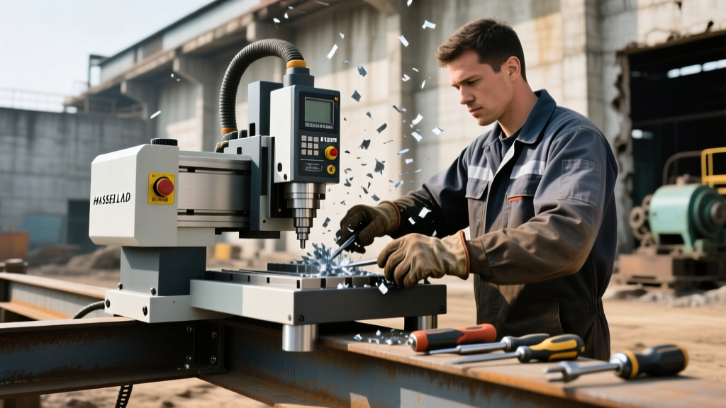
Mastering 3-Axis CAD CNC Machine Setup and Capabilities
Master 3-axis CAD CNC machine setup with expert operator workflows, workholding strategies, and capability limits for precision manufacturing.
Bridging the Digital-to-Physical Gap in 3-Axis Milling
Translating a complex 3D model into a physical part requires more than just pressing a cycle start button. The modern CAD CNC machine workflow demands that operators understand the kinematic limitations of 3-axis platforms, the nuances of CAM-generated toolpaths, and the physical realities of workholding. While 5-axis machining dominates aerospace headlines, the 3-axis vertical machining center (VMC) remains the backbone of global manufacturing, accounting for over 70% of all milled prismatic and contoured parts.
This guide details the exact setup protocols, capability boundaries, and failure-mode mitigations required to run a 3-axis CAD CNC machine efficiently in a 2026 production environment.
Defining 3-Axis CAD CNC Machine Capabilities and Limits
A standard 3-axis VMC operates on linear X, Y, and Z axes. The cutting tool approaches the workpiece exclusively from the top (Z-axis), meaning any geometry requiring a side approach or undercut must be re-fixtured or machined on a multi-axis platform.
⚠️ Capability Warning: The Undercut LimitationStandard 3-axis CAD CNC machine setups cannot machine internal undercuts or deep side pockets without specialized tooling (e.g., lollipop end mills or slotting cutters). If your CAD model features an internal O-ring groove on a vertical wall, a 3-axis machine will require a secondary horizontal setup, introducing a cumulative tolerance stack-up of ±0.001" to ±0.002" per flip.
2.5D vs. True 3D Contouring
Operators must distinguish between 2.5D and 3D toolpaths generated by CAM software like Mastercam or Autodesk Fusion:
- 2.5D Machining: The tool moves in X and Y simultaneously, but Z only moves at discrete depth levels (e.g., pocket clearing, drilling, 2D profiling). This allows for aggressive material removal rates (MRR) and rigid tooling.
- True 3D Contouring: X, Y, and Z axes interpolate simultaneously to machine complex organic shapes, molds, and dies. This requires ball-nose or bull-nose end mills and relies heavily on the machine's look-ahead processing and ball screw responsiveness to prevent dwell marks and scalloping.
The Operator’s Setup Workflow: From CAD to G-Code
A flawless setup prevents catastrophic crashes and ensures first-part correctness. Follow this exact sequence when loading a new CAD CNC machine program.
- CAM Verification and Gouge Checking: Before transferring code, run a solid-model simulation in your CAM software. Verify that the toolholder (not just the cutting tool) clears the workholding. A common failure mode is a CAT40 toolholder flange clipping a Kurt DX6 vise jaw during deep Z-axis contouring.
- Workholding and Parallel Selection: Clean the vise bed and parallels with a lint-free cloth and isopropyl alcohol. For 6061-T6 aluminum, use a 6-inch CNC vise clamped at 4,500 PSI. Ensure the part is seated dead-flat by striking it with a dead-blow mallet while applying final clamping pressure.
- Establishing the Work Offset (G54): Use a Renishaw OMP60 spindle probe or a Haimer 3D Sensor to pick up the X and Y datums. For the Z-axis, establish the Z-datum using a calibrated 2.000" gage block to avoid scratching the finished part surface.
- Tool Length Offset (TLO) Verification: Set the H-geometry offset for every tool. Critical: Always verify the TLO by jogging the tool to 1.0" above the part and checking the machine position against the physical distance. A 0.100" error in TLO will result in the spindle driving the tool directly into the workpiece at rapid traverse.
Never run a new CAD CNC machine program in continuous memory mode on the first part. Use Single Block mode, keep your hand on the Feed Hold button, and watch the Z-axis distance-to-go (DTG) display on the control panel. The DTG must reach zero exactly when the tool touches the programmed Z-zero surface.
Machine Specifications and 2026 Market Benchmarks
Understanding the physical rigidity and positioning accuracy of your specific VMC dictates how aggressive your CAD CAM parameters can be. Below is a comparison of two dominant 3-axis platforms in modern job shops.
| Specification | Haas VF-2SS (Super Speed) | Tormach 1500MX |
|---|---|---|
| Spindle Taper | CAT40 | BT30 / TTS |
| Max Spindle Speed | 12,000 RPM | 10,000 RPM |
| Positioning Accuracy | ±0.0002" (±0.005 mm) | ±0.0005" (±0.012 mm) |
| Rapid Traverse Rate | 1,400 IPM | 550 IPM |
| Approx. 2026 Loaded Cost | $95,000 - $105,000 | $22,000 - $26,000 |
According to training guidelines published by Haas Automation, maximizing the VF-2SS requires utilizing its high-speed machining (HSM) look-ahead features, which process up to 1,000 blocks of G-code ahead of the current position to smooth out 3D contours and prevent dwell marks.
Optimizing Feeds, Speeds, and Tool Deflection
The most common mistake operators make when executing a CAD CNC machine toolpath is ignoring the Length-to-Diameter (L/D) ratio of the cutting tool. Tool deflection scales with the cube of the stickout length.
"If you double the stickout of a 1/2-inch end mill, the tool deflection under the same cutting load increases by a factor of eight. Always use the shortest tool extension possible to maintain dimensional accuracy and prevent chatter." — Modern Machine Shop Workholding & Tooling Guidelines
Baseline Parameters for 6061-T6 Aluminum (3-Axis Profiling)
- Tool: 1/2" 3-Flute Carbide End Mill (AlTiN coated, 35° helix)
- Stickout: 1.25" (L/D ratio of 2.5:1)
- Spindle Speed: 10,500 RPM
- Feed Rate: 120 IPM (Inches Per Minute)
- Radial Depth of Cut (Stepover): 0.050" (10% of tool diameter for finishing)
- Axial Depth of Cut (Stepdown): 0.500" (1x diameter for roughing)
When programming these parameters in your Autodesk Fusion CAM environment, ensure 'Climb Milling' is selected for finishing passes to push the chip thickness to zero at the exit point, yielding a superior surface finish (typically Ra 32 µin or better).
Common Setup Failures and Edge Cases
Even with perfect CAD models, physical setup errors will scrap parts. Watch for these specific failure modes:
🚨 Critical Failure Mode: The G43 H-Geometry CrashIf your CAM software outputs G43 H01 but the operator accidentally loads Tool 2 into the spindle and sets the offset in the H02 register, the machine will apply the wrong tool length compensation. The control will drive the tool into the part by the exact difference in length between Tool 1 and Tool 2. Always verify the active tool number matches the active H-offset on the control screen before cycle start.
Managing Stringy Chips in Deep Pocketing
When machining deep pockets in ductile materials like 304 Stainless Steel or 6061 Aluminum, long stringy chips can wrap around the tool, causing re-cutting and tool breakage. To mitigate this without switching to a 5-axis machine:
- Use through-spindle coolant (TSC) at 300 PSI minimum to evacuate chips from deep cavities.
- Implement trochoidal milling (Dynamic Milling) toolpaths, which maintain a constant radial engagement and allow chips to break naturally due to the varying cutting forces.
- Apply compressed air blasts via programmable M-codes (e.g.,
M10to open air valve,M11to close) during retract moves.
Mastering the G-Code Bridge
While CAM software generates the code, an expert operator must be able to read and edit it at the control. Understanding the NIST RS274NGC standard for G-code interpretation is non-negotiable for advanced troubleshooting.
Consider this standard 3-axis safe-start block:
N100 G90 G17 G40 G80 G49 (Safe start: Absolute, XY plane, Cancel cutter comp, Cancel canned cycles, Cancel TLO)
N110 G28 G91 Z0 (Return Z to machine home)
N120 T01 M06 (Tool change to Tool 1)
N130 G00 G90 G54 X1.5 Y2.0 (Rapid to XY start position in Work Offset 1)
N140 G43 H01 Z1.0 (Apply Tool Length Offset 1, rapid to 1 inch above part)
N150 S10000 M03 (Spindle on CW at 10,000 RPM)
N160 M08 (Coolant on)
If a part is running 0.005" off in the X-axis due to thermal expansion of the ball screws after a 4-hour production run, the operator can simply shift the G54 X-offset by -0.005" at the control, rather than regenerating the entire CAD CNC machine toolpath in the CAM software.
Summary Checklist for 3-Axis Operators
- Verify CAM clearances: Check toolholder collision against vise jaws in simulation.
- Clean workholding: Zero debris on parallels and vise ways.
- Confirm TLOs: Match physical tool numbers to control H-offset registers.
- Respect L/D ratios: Minimize tool stickout to eliminate chatter and deflection.
- Single-block the first part: Monitor Z-axis DTG to prevent rapid crashes.
Mastering the 3-axis CAD CNC machine setup is about controlling variables. By rigorously enforcing workholding standards, verifying offsets, and understanding the physical limits of linear kinematics, operators can consistently hold ±0.0005" tolerances and produce flawless parts on the first cycle.