Inside Laser CNC Machines: Technical Specs and Cutting Physics
Explore the technical specifications, beam physics, and motion dynamics of fiber laser CNC machines, from resonator optics to assist gas matrices.
The Physics of Beam Generation: Fiber vs. CO2 Resonators
The core of modern laser CNC machines relies on stimulated emission to generate a coherent, monochromatic beam capable of vaporizing or melting industrial metals. While CO2 gas lasers (operating at a 10.6 µm wavelength) dominated the industry for decades, Ytterbium-doped (Yb) fiber lasers have become the definitive standard for metal fabrication due to their 1.06 µm (1064 nm) wavelength. This shorter wavelength is absorbed by metallic surfaces up to three times more efficiently than CO2 beams, fundamentally altering the thermal dynamics of the cut.
Inside a fiber laser resonator, pump diodes inject light into an optical fiber doped with rare-earth elements. This creates a population inversion, releasing photons that bounce between Fiber Bragg Gratings (FBGs) acting as mirrors. The resulting beam is delivered through a flexible, armored optical fiber cable directly to the cutting head, eliminating the complex, alignment-sensitive mirror articulation arms required by CO2 systems.
Wall-Plug Efficiency & Thermal Load: Modern high-power fiber sources (such as the IPG YLS series) achieve a wall-plug efficiency of 35% to 40%. In contrast, traditional CO2 resonators operate at roughly 10% to 15%. This efficiency delta means a 12kW fiber laser CNC machine requires significantly less electrical infrastructure and generates less ambient heat in the facility compared to a 6kW CO2 equivalent.Beam Delivery and Focal Spot Dynamics
Once the raw laser beam exits the delivery fiber, it enters the collimation and focusing assembly. The raw beam is divergent; the collimating lens captures this divergence and creates a parallel beam path. The focusing lens then concentrates this parallel light into a microscopic focal spot on the material surface.
Optical Path and Lens Selection
The diameter of the focal spot dictates the power density (measured in MW/cm²), which directly influences the machine's ability to pierce thick plates and maintain a narrow kerf. Operators must select focal lengths based on material thickness:
- Short Focal Length (e.g., 5-inch / 127mm): Produces a tiny focal spot (approx. 0.1mm) with extreme power density. Ideal for thin-gauge sheet metal (under 3mm) where high-speed contouring and minimal heat-affected zones (HAZ) are critical.
- Long Focal Length (e.g., 7.5-inch to 10-inch / 190mm to 254mm): Creates a larger focal spot but provides an extended Rayleigh length (depth of focus). This is mandatory for cutting thick plate (15mm to 30mm+), ensuring the beam maintains sufficient energy density through the entire depth of the material.
According to technical documentation from TRUMPF laser cutting systems, maintaining pristine optics is non-negotiable; a single microscopic slag splatter on a protective window can cause thermal lensing, warping the beam path and destroying the focusing lens within seconds.
The Cutting Head Assembly and Z-Axis Control
The cutting head is a highly calibrated electromechanical assembly. Advanced models, such as the Precitec ProCutter series, integrate closed-loop monitoring sensors that track optical temperature and internal pressure in real time. If the protective window exceeds safe thermal thresholds, the CNC controller halts the machine to prevent catastrophic optical failure.
Z-axis height control is managed by a capacitive sensor ring surrounding the copper nozzle. This sensor measures the electrical capacitance between the nozzle tip and the conductive metal sheet, maintaining a precise standoff distance (typically 0.5mm to 1.0mm). Because raw sheet metal is rarely perfectly flat, the capacitive sensor dynamically adjusts the Z-axis servo motor at high speeds, ensuring the focal point remains exactly on or slightly below the material's bottom surface throughout the cutting path.
Assist Gas Matrix: Exothermic vs. Endothermic Cutting
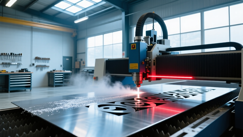
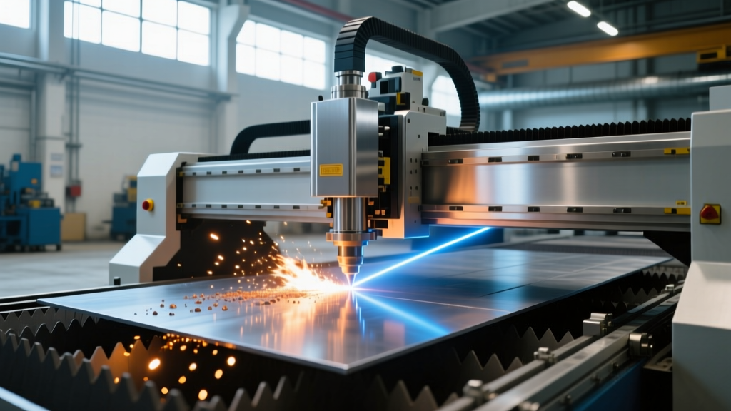
The laser beam alone does not remove material; it merely melts or vaporizes it. The assist gas, delivered coaxially through the nozzle at high pressure, ejects the molten slag from the kerf. The choice of gas fundamentally changes the thermodynamics of the cut.
| Material | Assist Gas | Pressure Range | Thermodynamic Mechanism | Edge Quality Result |
|---|---|---|---|---|
| Mild Steel (up to 25mm) | Oxygen (O2) | 0.8 - 2.5 bar | Exothermic: Iron oxidizes, releasing additional heat that aids the laser. | Oxide layer present; requires secondary cleaning for welding/painting. |
| Stainless Steel / Aluminum | Nitrogen (N2) | 12 - 25 bar | Endothermic: Inert gas purely melts and blows out material without oxidation. | Clean, oxide-free edge; ready for immediate powder coating or welding. |
| Thin Gauge Mixed Metals | Compressed Air | 10 - 16 bar | Hybrid: Contains oxygen and nitrogen; balances speed and edge quality. | Slight oxidation; highly cost-effective for non-critical structural parts. |
When cutting mild steel with oxygen, the striation pattern (the characteristic drag lines on the cut edge) is governed by the oxidation wave front. If the feed rate is too high, the wave front lags, causing severe dross (slag) adhesion on the bottom edge. If the feed rate is too slow, the kerf widens, and the edge burns excessively, creating a rough, pitted surface.
Gantry Motion Systems: Linear Drives vs. Rack-and-Pinion
The kinetic performance of a laser CNC machine dictates its ability to process complex geometries with tight corner tolerances. The motion system must accelerate and decelerate the heavy cutting head gantry without introducing positional lag or vibration.
Helical Rack and Pinion
The industry standard for large-format beds (e.g., 1.5m x 3m or larger). Helical gears provide a higher contact ratio than spur gears, resulting in smoother motion and reduced backlash. Modern systems pair these with high-resolution absolute encoders, achieving positioning accuracies of ±0.03mm. However, mechanical limits restrict peak acceleration to roughly 1.5G to 2.0G.
Linear Motor Drives
Reserved for premium, high-speed machines, linear motors eliminate mechanical transmission components (gears, belts, racks) entirely. The gantry is propelled by magnetic fields, allowing for blistering accelerations of 3.0G to 4.0G. This is critical for "fly-cutting" or "wobble-cutting" ventilation hole patterns, where the machine must execute thousands of rapid directional changes per minute. The trade-off is cost and thermal management; linear motors generate immense heat and require dedicated liquid cooling circuits integrated into the machine bed.
High-Power Specifications: 6kW to 30kW Fiber Lasers
The evolution of high-power fiber sources has dramatically shifted the thickness capabilities of laser CNC machines. According to application data from IPG Photonics, scaling power does not just increase speed; it unlocks entirely new thickness thresholds for nitrogen cutting.
| Source Power | Approx. System Cost (2026) | Max Mild Steel (O2) | Max Stainless (N2) | Pierce Time (12mm MS) |
|---|---|---|---|---|
| 6 kW | $140,000 - $180,000 | 25 mm | 15 mm | 1.8 seconds |
| 12 kW | $220,000 - $280,000 | 30 mm | 30 mm | 0.6 seconds |
| 20 kW | $350,000 - $420,000 | 40 mm | 40 mm | 0.2 seconds |
| 30 kW | $500,000+ | 50 mm+ | 50 mm+ | < 0.1 seconds |
At the 30kW tier, machines utilize specialized multi-stage piercing routines. Instead of a single continuous blast that creates a massive crater of molten slag, the CNC controller pulses the beam at varying frequencies and focal positions, progressively drilling a clean, narrow pilot hole before transitioning to the cutting vector.
Failure Modes and Edge Cases in Reflective Material Processing
Processing highly reflective materials like copper, brass, and pure aluminum introduces severe edge cases. At room temperature, copper reflects over 90% of a 1064 nm fiber laser beam. If the beam is not absorbed, it reflects directly back up through the nozzle, into the cutting head, and down the delivery fiber, potentially destroying the multi-million-dollar laser source.
To mitigate back-reflection damage, modern laser CNC machines employ several hardware and software safeguards:
- Optical Isolators: Hardware components installed near the source that allow light to travel in only one direction, absorbing backward-traveling photons.
- Beam Wobble Technology: The cutting head utilizes a high-speed oscillating mirror to move the focal spot in a figure-eight or circular pattern. This widens the kerf, prevents the beam from reflecting straight back up the optical axis, and ensures consistent energy distribution across highly conductive metals.
- Anti-Reflective Coatings: All internal lenses and protective windows are treated with specialized dielectric coatings designed to transmit 1064 nm light while safely scattering off-axis reflections.
Operators must strictly avoid cutting reflective materials with damaged nozzles or degraded protective windows. A compromised optical path reduces the machine's ability to detect back-reflections, turning a routine copper busbar cutting job into a catastrophic equipment failure.