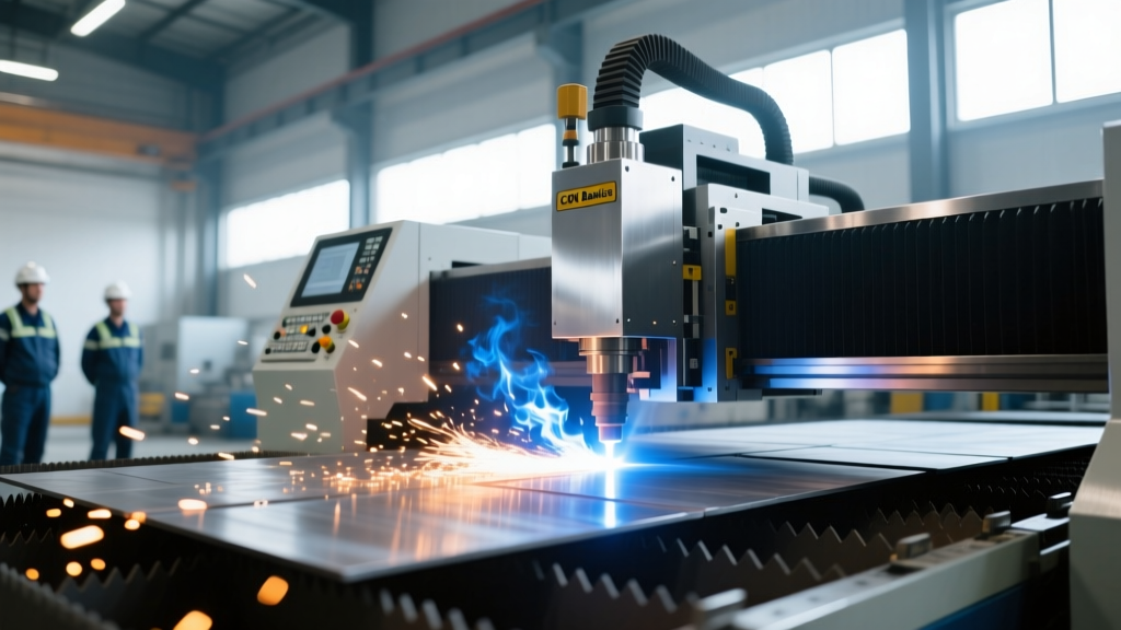
How a CNC Machine Works: An Operator Training & Setup Guide
Master how a CNC machine works with this operator training guide. Learn kinematics, setup protocols, workholding torque specs, and troubleshooting.
The Core Architecture: Translating G-Code to Physical Motion
Understanding how a CNC machine works requires moving beyond basic button-pushing to grasp the closed-loop kinematic systems driving the equipment. Modern 3-axis Vertical Machining Centers (VMCs), such as the Haas VF-2SS or DMG MORI CMX 600V, rely on a synchronized network of servo motors, ball screws, and linear guideways to achieve positional accuracies within 0.0002 inches (5 microns).
When an operator loads a program into a Fanuc 0i-F Plus or Siemens Sinumerik ONE control, the controller interpolates the G-code toolpath. It sends voltage signals to the axis servo drives (commonly Yaskawa or Mitsubishi units). These drives power the servo motors, which rotate precision-ground ball screws—typically with a 10mm or 12mm pitch. The ball screws translate rotational force into linear motion along THK or Rexroth linear guideways.
Operator Alert: Following ErrorsThe control constantly monitors the motor's rear-mounted encoder (often resolving at 131,072 pulses per revolution). If the physical axis lags behind the commanded position by more than the parameter threshold (usually 0.0004 inches), the control triggers a 'Following Error' alarm and halts motion to prevent a crash. Never increase this parameter mask to bypass an alarm; it indicates mechanical binding or a failing servo drive.
Step-by-Step Operator Workflow: From CAD to Chip
Proper machine operation follows a rigid sequence to ensure datum alignment and toolpath verification. Deviating from this workflow is the primary cause of spindle crashes and scrapped parts.
| Phase | Operator Action | Equipment / Specification |
|---|---|---|
| 1. Thermal Stabilization | Run spindle warm-up macro to expand bearings evenly. | 10-15 mins at 50% max RPM (e.g., 6,000 RPM on a 12k spindle). |
| 2. Workholding Setup | Mount vise, indicate fixed jaw, and torque clamps. | Kurt DX6 Vise; 90 ft-lbs on handle for 11,000 lbs clamping force. |
| 3. Datum Establishment | Pick up X/Y zero and Z part surface. | Renishaw OMP60 spindle probe; feed rate <100 mm/min. |
| 4. Tool Length Offsets | Measure Z-length for all tools in the carousel. | Renishaw TS27R tool setter; verify repeatability to 1 micron. |
| 5. Dry Run / Verify | Run program with Z-axis shift +2.0 inches and rapid override at 25%. | Control graphics and physical air-cutting verification. |
Workholding and Kinematic Rigidity
A fundamental aspect of how a CNC machine works is the transfer of cutting forces through the tool, into the spindle, and down through the workpiece to the machine table. If the workholding yields, the machine's inherent rigidity is irrelevant.
Clamping Force and Material Deflection
When machining 6061-T6 aluminum, excessive clamping force on thin walls will cause elastic deformation. When the part is unclamped, it springs back out of tolerance. For thin-walled components, operators must transition from standard steel jaws to custom-machined 6061 aluminum soft jaws that support the entire perimeter of the part, distributing the clamping load and reducing required torque to 30-40 ft-lbs.
According to Sandvik Coromant's milling knowledge base, maintaining a rigid setup is critical for managing cutting forces and preventing chatter, which directly impacts tool life and surface finish quality.
Troubleshooting Common Kinematic and Cutting Errors
Operators must diagnose issues based on physical evidence left on the workpiece and the behavior of the machine axes.
Symptom: Chatter Marks on Floor
Root Cause: Tool overhang exceeds the critical Length-to-Diameter (L:D) ratio, causing harmonic vibration during radial engagement.
Operator Fix: Reduce L:D ratio to less than 4:1 for solid carbide endmills. If deep cavities require longer reach, switch to a carbide shank or anti-vibration boring bar, and reduce radial depth of cut (RDOC) to 5% of tool diameter.
Symptom: Z-Axis Dimensional Drift
Root Cause: Thermal growth in the spindle housing or ball screw friction heating. A cold machine will drift up to 0.003 inches in Z over the first hour of operation.
Operator Fix: Execute the OEM spindle warm-up macro every morning and after any idle period exceeding 4 hours. Use G10 commands to update Z-offsets dynamically if running untended lights-out shifts.
Coolant Delivery and Chip Evacuation
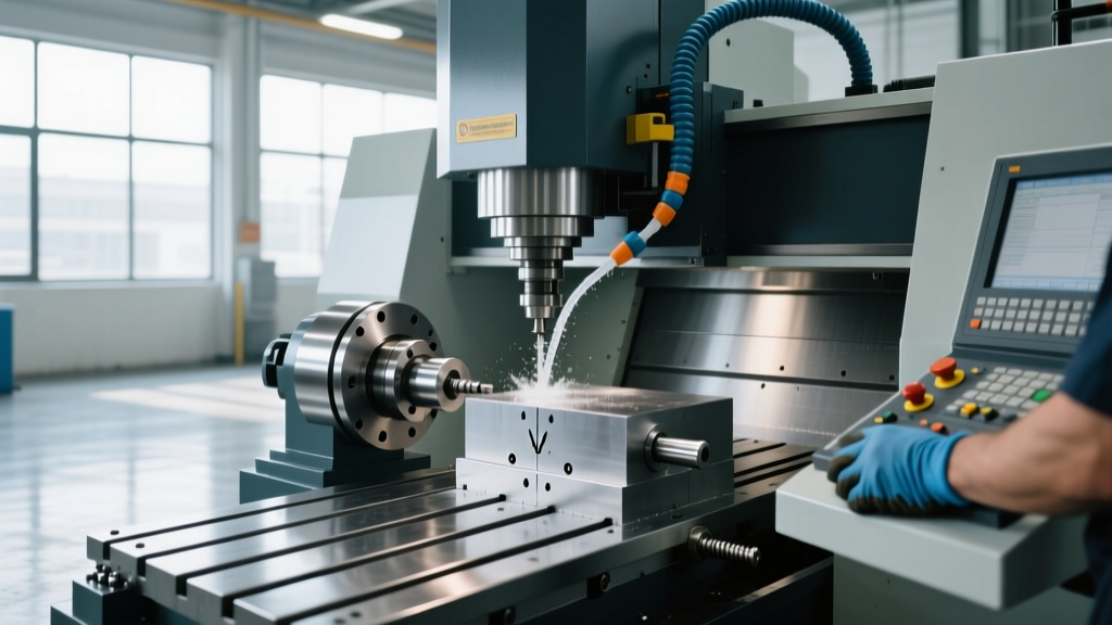
The mechanical motion of a CNC machine is only half of the machining equation; the other half is thermal management. High-pressure through-spindle coolant (TSC) systems, operating at 300 to 1,000 PSI, penetrate the cutting zone to break the chip and prevent built-up edge (BUE).
- Flood Coolant (Standard): Operates at 30-50 PSI. Suitable for general roughing in steel and aluminum where chip volume is high but cutting temperatures remain moderate.
- Through-Tool Coolant (TSC): Required for deep cavity milling and drilling. The coolant exits directly through the tool flutes, evacuating chips that would otherwise pack and snap the tool.
- Mist / MQL (Minimum Quantity Lubrication): Uses compressed air to atomize microscopic oil droplets. Ideal for high-speed machining (HSM) of aluminum, where flood coolant would cause thermal shock to the hot carbide tool.
Safety Protocols and Interlock Systems
Modern CNC machines are enclosed in polycarbonate and steel cabins designed to contain high-velocity projectiles. A broken 1/2-inch carbide endmill spinning at 12,000 RPM possesses lethal kinetic energy. The OSHA Machine Guarding standards mandate strict adherence to physical and electrical safety interlocks.
"Never bypass the door safety interlock switch using tape or zip-ties. If the interlock fails, the machine must be locked out and repaired. Bypassing this switch removes the immediate axis-feed halt that occurs when the door is opened during an active cycle, exposing the operator to uncontained rotating mass and flying swarf."
E-Stop Recovery Protocol
When an Emergency Stop is pressed, the control drops the servo brakes and cuts power to the spindle drive. Recovering from an E-stop requires more than simply twisting the button to release it.
- Clear the Fault: Release the E-stop button and press the 'Reset' key on the control panel.
- Re-home the Axes: The machine has lost its absolute positional reference. You must manually jog all axes away from the workpiece, then execute a Zero Return (G28) to re-establish the machine coordinate system.
- Inspect the Tool: An E-stop halts the spindle instantly, which often chips the cutting edges of the tool engaged in the cut. Inspect the tool under magnification before resuming the cycle.
- Verify Work Offsets: Ensure the workpiece did not shift in the vise during the sudden deceleration. Re-probe the X/Y datums if the crash forces were severe.
For advanced training on CNC accuracy and metrology, operators should consult the NIST Advanced Manufacturing guidelines, which detail the standardized testing procedures for evaluating machine tool volumetric accuracy and geometric alignment.
Summary of Operator Best Practices
Mastering how a CNC machine works means respecting the physical limits of its components. Maintain strict thermal stabilization routines, adhere to precise workholding torque specifications, and never override safety interlocks. By treating the machine as a closed-loop kinematic system rather than a simple automated drill press, operators drastically reduce scrap rates, extend spindle bearing life, and ensure consistent micron-level tolerances across high-volume production runs.