What Is a CNC Lathe Machine? Core Operator Training
Learn what a CNC lathe machine is through an operator's lens. Master pre-flight checks, workholding, G-code safety, and crash prevention.
The Textbook vs. The Shop Floor: What Is a CNC Lathe Machine?
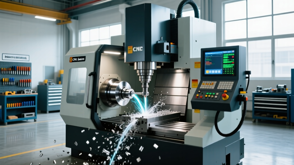
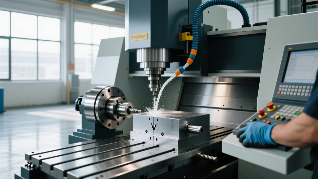
When a new trainee asks, "what is a cnc lathe machine," the textbook definition is straightforward: a computer-controlled machine tool where the workpiece rotates on a spindle while stationary cutting tools remove material to create cylindrical, conical, or spherical geometries. However, from an operator's perspective, a modern CNC turning center is a high-torque, high-precision kinetic system that demands rigorous adherence to safety and setup protocols.
Unlike manual engine lathes, a CNC (Computer Numerical Control) lathe utilizes servo motors and ball screws to position the turret and tailstock with micron-level repeatability. According to Sandvik Coromant's metal cutting knowledge base, modern turning operations rely heavily on the synchronization of spindle speed (RPM) and feed rate (IPR or MMPR) to optimize chip control and tool life. Understanding the machine's anatomy is the first step toward operating it safely and profitably.
Core Kinematic Components:- Headstock & Main Spindle: Houses the main drive motor and spindle bearings. High-end models use liquid-cooled spindles to mitigate thermal growth during long production runs.
- Turret: The rotating tool carrier. Can be configured with VDI, BMT, or Hirth coupling interfaces, holding anywhere from 8 to 24 live or static tools.
- Slideways & Ball Screws: Linear guides (box ways or linear rails) that dictate the X and Z axis movements, driven by precision ground ball screws.
- Chip Conveyor & Coolant System: High-pressure coolant pumps (often 1,000 to 3,000 psi) designed to break stringy chips common in materials like 304 stainless steel or Inconel.
Machine Class Matrix: Capability and Investment
Not all CNC lathes are built for the same work. Operators must understand the limitations of their specific machine class to avoid overloading the turret or attempting impossible geometries. Below is a breakdown of standard industry configurations and their approximate 2026 capital equipment costs.
| Machine Class | Representative Model | Axis Configuration | Approx. Cost (USD) | Primary Application |
|---|---|---|---|---|
| 2-Axis Standard | Haas ST-10 | X, Z (C-axis optional) | $65,000 - $85,000 | High-volume OD/ID turning, simple facing and boring. |
| Y-Axis Turning | Doosan Lynx 2100Y | X, Y, Z, C | $115,000 - $145,000 | Off-center milling, polygon turning, complex flats. |
| Mill-Turn / Multi-Task | Mazak Integrex i-200 | 5-Axis Simultaneous | $250,000 - $400,000+ | Done-in-one machining, aerospace structural components. |
The Operator’s Pre-Flight Verification Protocol
Skip the pre-flight check, and you risk catastrophic failure. Before pressing the green cycle start button, veteran operators execute a rigid verification sequence. The Haas Automation technical tips library frequently emphasizes that 80% of first-shift crashes are caused by skipped setup verifications.
- Verify Way Lube and Hydraulic Pressures: Check the way lube pressure gauge; it should read between 15 and 20 psi to ensure the linear rails are properly lubricated (typically using Mobil Vactra No. 2). Verify the hydraulic chuck pressure. For an 8-inch Kitagawa B-210 chuck, standard pressure is 350 psi for 6061 aluminum, but must be increased to 450-500 psi for heavy interrupted cuts in 4140 steel.
- Check Chuck Runout (TIR): Mount a test bar or indicate the master jaw faces. Total Indicator Runout (TIR) must be less than 0.0005 inches. If runout exceeds this, the spindle bearings may be compromised, or the chuck mounting adapter requires cleaning.
- Validate Tool Offsets (Geometry vs. Wear): Ensure that the Geometry offsets contain the machine coordinate positions from your tool presetter or touch-off, while the Wear offsets are zeroed out before the first part. Mixing these up guarantees a crash or scrap parts.
- Confirm Work Coordinate System (G54): Verify the Z-axis work shift. A common error is leaving a Z-shift from a previous setup in the control, causing the tool to plunge into the chuck face.
- Dry Run with Single Block & Rapid Override: Run the first part with Single Block active, Optional Stop on, and Rapid Override dialed down to 5%. Keep your hand on the Feed Hold button.
Workholding Dynamics and Tooling Rigidity
Chuck Pressure and Material Yield
Operators often assume that maximum hydraulic pressure equals maximum safety. This is false. Over-pressurizing a chuck on a thin-walled tube or soft material (like Delrin or thin-wall aluminum) will cause elastic deformation. When the chuck releases, the part springs back out of round, resulting in scrapped components. Always calculate the required clamping force based on the cutting forces generated by your specific feed rate and depth of cut, factoring in centrifugal force reduction at high RPMs.
Turret Interfaces: VDI vs. BMT
Understanding your turret interface is critical for tool selection. VDI (DIN 69880) toolholders use a serrated coupling and a single clamping pin. While quick to change, they lack the rigidity for heavy roughing. BMT (Bolt-on Mounting Tool) interfaces use a larger face coupling secured by four or more bolts. If you are taking 0.250-inch depth of cut passes in titanium or Inconel, BMT tooling reduces overhang and chatter significantly, extending insert life by up to 30%.
Crash Prevention: The G96 Centrifugal Hazard
One of the most lethal mistakes a novice operator can make involves Constant Surface Speed (G96). G96 commands the control to maintain a specific surface cutting speed (e.g., 500 SFM) by automatically increasing the spindle RPM as the tool moves closer to the centerline (X0).
CRITICAL SAFETY WARNING:If G96 is active and the tool is commanded to X0 without a spindle speed clamp, the RPM will theoretically approach infinity. In reality, the centrifugal force will overcome the hydraulic clamping force of the chuck jaws long before the spindle reaches max RPM. The jaws will eject from the chuck, destroying the machine guards and posing a fatal risk to the operator.
The Fix: Always program a G50 (or G922 on some controls) maximum spindle speed limit before calling G96. Example:
G50 S3500 (Limits spindle to 3500 RPM max) followed by G96 S500.
Mastering what a CNC lathe machine is goes far beyond memorizing its parts. It requires an intimate understanding of kinematics, material science, and control logic. By adhering to strict pre-flight protocols, respecting workholding physics, and understanding the hidden dangers in G-code modal states, operators transition from mere button-pushers to highly skilled manufacturing technicians. For comprehensive safety standards regarding rotating machinery and entanglement hazards, operators should regularly review the OSHA machine safeguarding guidelines to ensure their shop floor remains compliant and secure.