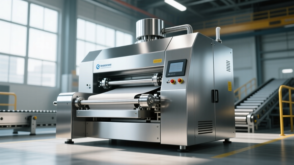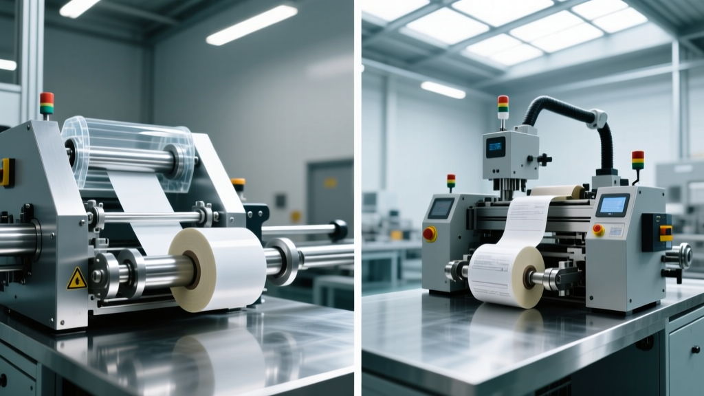
Shrink Packaging Machinery in FFS Lines: 2026 Case Studies
Explore how shrink packaging machinery integrates with form-fill-seal systems. Real 2026 case studies, CapEx data, and film specs for multi-pack lines.
Integrating primary form-fill-seal (FFS) equipment with secondary bundling systems remains one of the most complex engineering challenges in modern packaging lines. While FFS technology excels at high-speed primary containment, downstream shrink packaging machinery is required to unitize multi-packs, stabilize pallet loads, and provide tamper-evident retail displays. In 2026, the focus has shifted from standalone machines to fully synchronized, servo-driven ecosystems communicating via OPC-UA protocols.
This guide examines the technical handoff between FFS outputs and shrink tunnels, featuring applied case studies, material science parameters, and capital expenditure (CapEx) breakdowns for integrated lines.
Architectural Integration: Syncing FFS with Shrink Packaging Machinery
The primary failure point in combined lines is the accumulation table between the FFS discharge and the shrink wrapper infeed. If a vertical FFS (VFFS) system discharges pouches at 80 bags per minute (bpm) into a continuous-motion side-seal shrink wrapper, the pitch (spacing) must be perfectly maintained.
Integration Standard: Modern lines utilize Allen-Bradley or Siemens PLCs with PackML (ISA-TR88) state models. This allows the shrink packaging machinery to automatically throttle its conveyor speed and tunnel temperature if the upstream FFS machine faults or slows down, preventing film burn-through during line stops.According to automation guidelines published by PMMI (The Association for Packaging and Processing Technologies), standardized machine-to-machine communication reduces micro-stoppes at the FFS-to-shrink handoff by up to 18%, directly boosting Overall Equipment Effectiveness (OEE).
Material Science: Selecting Shrink Films for FFS Outputs
The choice of shrink film dictates the tunnel architecture. FFS lines producing heavy, sharp-edged primary packs (like stand-up pouches with zippers) require different secondary films than lines producing lightweight retail boxes.
| Film Type | Thickness Range | Shrink Temp (°C) | Tensile Strength | Best FFS Application |
|---|---|---|---|---|
| Polyethylene (PE) | 1.5 - 3.0 mil | 160°C - 175°C | Very High | Heavy multi-packs, beverage cans, large VFFS bags |
| Polyolefin (POF) | 45 - 100 gauge | 120°C - 150°C | Moderate | Retail display bundling, HFFS carton overwraps |
| PVC (Polyvinyl Chloride) | 75 - 100 gauge | 110°C - 130°C | Low/Brittle | Legacy systems, rigid HFFS blister packs (declining use) |
As noted by the Flexible Packaging Association, PE remains the dominant choice for heavy-duty tertiary bundling due to its superior puncture resistance and compatibility with store drop-off recycling streams, whereas POF is preferred for its optical clarity in retail-ready FFS carton bundling.
Case Study 1: High-Speed Beverage Multi-Pack Bundling
The Scenario
A regional craft brewery needed to transition from manual 6-pack ring carriers to automated shrink-bundled corrugated trays to reduce material costs and improve line throughput. The line utilizes a horizontal FFS (HFFS) system to erect corrugated trays, load 12-oz aluminum cans, and transfer them to the shrink wrapper.
Machinery Configuration & Metrics
- Upstream FFS: Continuous-motion HFFS tray erector and loader (Speed: 65 trays/min).
- Shrink Packaging Machinery: Continuous-motion side-seal wrapper with a 12-foot recirculating heat tunnel.
- Film: 2.0-mil printed Polyethylene (PE) with a low-friction slip additive.
- Tunnel Parameters: Pre-heat zone at 140°C, main shrink zone at 170°C, cool-down zone with forced ambient air.
- Conveyor: Silicone-covered live rollers to prevent PE film from sticking during the molten phase.
Case Study 2: Pharmaceutical Sterile Tray Shrink Wrapping
The Scenario
A medical device manufacturer packages diagnostic kits in an ISO 7 cleanroom. The primary packaging is a sterile barrier pouch created on a VFFS machine. The secondary packaging requires a tamper-evident, dust-proof shrink overwrap without compromising the primary sterile seal via excessive heat.
Machinery Configuration & Metrics
Unlike the heavy-duty beverage line, this application requires extreme thermal control. The latest advancements in form-fill-seal thermal management allow for precise heat dissipation, but the downstream shrink tunnel must also be carefully calibrated.
- Primary FFS: VFFS system running 75-gauge Tyvek/film laminate at 30 bpm.
- Shrink Wrapper: L-Sealer with a center-fold film delivery system using 60-gauge POF.
- Thermal Guardrails: The shrink tunnel is restricted to a maximum of 135°C. Dwell time in the tunnel is precisely 3.8 seconds.
- Airflow Dynamics: Laminar, low-velocity cross-flow air is used to prevent the lightweight VFFS pouches from shifting or tumbling on the Teflon mesh belt.
Failure Mode Avoidance
During initial commissioning, the line experienced "dog-earing" (protruding, unshrunk film corners). This was traced to the VFFS output creating a micro-climate of trapped air inside the primary pouch. When the POF film shrank, the expanding trapped air inside the primary pack pushed against the secondary film. The fix involved adding a micro-perforation needle to the VFFS discharge belt to vent the primary pouch before it entered the L-sealer.
Troubleshooting Thermal Bottlenecks at the FFS-Shrink Handoff
When integrating shrink packaging machinery with FFS equipment, thermal and mechanical mismatches cause 80% of unplanned downtime. Below is a diagnostic matrix for common integration failures.
| Symptom | Root Cause | Engineering Fix |
|---|---|---|
| Seal bar burn-through on POF | Dwell time exceeds 1.2s during FFS upstream micro-stops. | Install a capacitive proximity sensor to auto-lift the seal bar if the line stops for >0.5s. |
| Film "ballooning" in tunnel | VFFS traps excess air; no venting mechanism. | Add mechanical squeeze rollers or perforation pins at the FFS discharge conveyor. |
| Skewed print registration on PE | Inconsistent tension between FFS accumulation table and wrapper infeed. | Replace gravity rollers with servo-driven lug conveyors synced to the wrapper's photocell. |
| Tunnel condensation / wet film | Moisture from FFS cooling jaws migrating into the heat tunnel. | Extend the accumulation conveyor by 6 feet and add overhead forced-air knives. |
CapEx and ROI Projections for Integrated Lines
Budgeting for a synchronized FFS and shrink packaging line requires accounting for both the primary and secondary machinery, as well as the integration engineering. Based on 2026 market pricing for mid-to-high-tier European and North American OEMs (e.g., Syntegon, Krones, Schneider), capital requirements scale with speed and hygiene ratings.
- Entry-Level Integration (30-45 cpm): $110,000 – $160,000. Includes a semi-automatic VFFS/HFFS and an L-sealer with a standard recirculating tunnel. Suitable for contract packagers with frequent changeovers.
- Mid-Range Continuous Motion (60-90 cpm): $185,000 – $280,000. Features fully automatic HFFS tray loading, side-seal wrappers with servo-driven film delivery, and multi-zone PLC-controlled tunnels.
- High-Speed / Cleanroom (120+ cpm): $350,000 – $550,000+. Includes stainless-steel washdown construction, integrated vision inspection systems at the FFS discharge, and advanced OPC-UA data tracking for OEE reporting.
"The highest ROI in secondary packaging doesn't come from buying the fastest shrink tunnel; it comes from minimizing the footprint and mechanical complexity of the accumulation conveyor between the FFS and the wrapper. Every inch of transfer belt is a potential jam point." — Lead Packaging Automation Engineer, Tier-1 Beverage Integrator
Final Sourcing Directives
When specifying shrink packaging machinery to follow an FFS system, mandate that the OEM provide a unified HMI (Human-Machine Interface). Operators should be able to adjust the FFS bag length and the shrink tunnel conveyor speed from a single touchscreen. Furthermore, require the shrink tunnel manufacturer to provide CFD (Computational Fluid Dynamics) modeling of the tunnel airflow based on your specific FFS output dimensions to guarantee uniform heat distribution before the equipment is built.