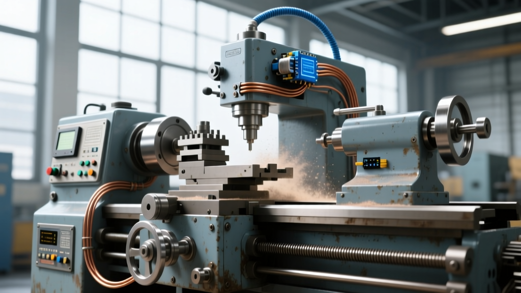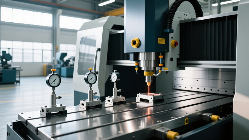
Chip Conveyor Specs for Your Precision Tool and Machine Setup
Explore technical specifications, chip morphology matching, and integration parameters for machine tool chip conveyors to protect your precision tool and machine.
Swarf accumulation is the primary mechanical and thermal threat to CNC accuracy and uptime. When outfitting a modern manufacturing cell, safeguarding your precision tool and machine investment requires more than simply bolting on a standard auger or belt system. Effective chip evacuation demands exact alignment between chip morphology, coolant flow rates, and conveyor drive mechanics. Misalignment results in way cover compression failures, linear guide scoring, and catastrophic gearbox shearing.
Thermal Distortion Warning: Trapped swarf acts as a thermal insulator on the machine bed. A 50 kg mass of retained steel chips can transfer enough residual heat to induce a 15-micron thermal growth error on a standard VMC Y-axis over a 4-hour shift, entirely negating the volumetric compensation of your precision tool and machine setup.Matching Conveyor Architecture to Chip Morphology
Selecting the correct conveyor requires classifying the primary chip type generated by your specific material and cutting parameters. The Society of Manufacturing Engineers (SME) categorizes chip evacuation challenges into three primary morphological groups, each demanding distinct mechanical solutions.
| Chip Morphology | Typical Materials | Required Conveyor Type | Critical Specification |
|---|---|---|---|
| Long, Stringy (Type 1) | 304 SS, Low-Carbon Steel, Titanium | Hinge Belt with Cleats | 2.5-inch pitch, UHMW wiper plates |
| Brittle, Fragmented (Type 2) | Cast Iron, High-Silicon Aluminum, Brass | Magnetic or Scraper | Neodymium magnet arrays, 15 FPM belt speed |
| Fines and Sludge (Type 3) | Grinding swarf, Swiss-type micro-chips | Back-flushing Drum Filter / Vacu-Flush | 20-micron filtration, 50+ GPM coolant flow |
Hinge Belt Conveyors: Drive and Pitch Specifications
For heavy turning operations producing stringy chips, the hinge belt conveyor remains the industry standard. Manufacturers like Mayfran International engineer these systems with specific pitch dimensions to prevent chip wedging. A 2.5-inch (63mm) pitch is mandatory for heavy-duty lathes, while a 1.5-inch (38mm) pitch is optimized for machining centers handling smaller, fragmented aluminum chips.
The drive motor must be paired with a mechanical torque limit switch. Standard setups utilize 1/4 HP to 3/4 HP, 3-phase gearmotors. The torque limiter must be calibrated to trip at exactly 110% of the nominal running torque. If a stringy chip 'birdnests' around the headshaft, the limiter disengages the drive within 0.5 seconds, preventing the shearing of the drive key or permanent gearbox damage.
Scraper and Magnetic Systems for Fines
When machining cast iron or utilizing high-pressure coolant (HPC) on aluminum, chips break into abrasive fines. Standard hinge belts allow these fines to slip between the hinges, destroying the belt track. Scraper conveyors utilize a continuous chain dragging polyurethane scrapers across the trough floor. For magnetic conveyors, neodymium magnet arrays pull ferrous fines through the coolant stream, requiring a minimum belt speed of 15 FPM to prevent sludge buildup on the magnet rings.
CNC Integration and PLC Synchronization
A conveyor operating independently of the machine tool cycle creates coolant starvation and overflow risks. Modern integration requires direct PLC I/O mapping to synchronize chip evacuation with high-pressure coolant pumps.
Standard M-Code Mapping Parameters
- M31: Conveyor Forward (Triggered 2.0 seconds after M08 Coolant On to allow fluid settling).
- M32: Conveyor Reverse (Utilized for 5 seconds every 45 minutes to clear headshaft birdnesting).
- M33: Conveyor Stop (Triggered simultaneously with M09 Coolant Off).
- M50 (Custom): Air-blast purge cycle for telescoping way covers (fires every 30 minutes for 3 seconds at 80 PSI).
When utilizing 1000 PSI (70 bar) high-pressure coolant systems, the conveyor trough must be constructed from 12-gauge (2.5mm) stainless steel. Standard 14-gauge troughs will deform under the hydraulic shock and splashback of HPC systems, leading to coolant leaks onto the shop floor.
Troubleshooting Matrix: Failure Modes and Technical Fixes
Even highly specified systems experience edge-case failures. Below is a diagnostic matrix for common swarf management breakdowns.
| Symptom | Root Cause Analysis | Technical Fix / Modification |
|---|---|---|
| Headshaft Birdnesting | Stringy chips bypassing the discharge wiper plate. | Replace standard steel wipers with UHMW polyethylene wiper plates; adjust gap to 0.015 inches. |
| Motor Burnout / Overheating | Torque limiter set too high; slipping clutch generating excess friction heat. | Recalibrate torque limiter to 110% of running load; install thermal overload relays on the motor starter. |
| Coolant Starvation at Pump | Fines blinding the return screen; conveyor running too fast, creating turbulence. | Reduce conveyor speed to 20 FPM; install a secondary 50-micron pre-filter screen in the return trough. |
| Way Cover Compression Failure | Chips packing into the bellows, preventing full axis travel. | Implement automated M50 air-blast purges; install heavy-duty chip deflectors above the X-axis way covers. |
2026 Sourcing and Cost Benchmarks
Capital expenditure for swarf management scales directly with integration complexity and filtration requirements. Based on current industrial pricing, machine shop managers should budget according to the following tiers:
- Standard Hinge Belt (10-foot run, 1/4 HP): $5,500 – $8,200. Suitable for standard VMCs and low-volume turning.
- Heavy-Duty Scraper with Integrated Filtration (50 GPM): $12,000 – $16,500. Required for cast iron milling and high-volume aluminum aerospace contracts.
- High-Pressure Integrated Vacu-Flush System (1000+ PSI capable): $18,000 – $26,000+. Mandatory for deep-hole drilling, Swiss-type lathes, and titanium machining cells.
Preventative Maintenance Intervals
To maintain the operational integrity of your precision tool and machine environment, adhere to strict teardown and inspection intervals. Neglecting these intervals shifts the failure mode from minor wear to catastrophic mechanical seizure.
- Weekly (40 Hours): Inspect UHMW wiper plates for gouging. Measure the gap between the wiper and the belt; if it exceeds 0.030 inches, replace the wiper to prevent stringy chip infiltration.
- Monthly (200 Hours): Check gearbox oil levels (typically ISO VG 220 or 320 gear oil). Inspect the mechanical torque limit switch for proper calibration by manually stalling the belt and verifying the clutch disengagement.
- Bi-Annually (1000 Hours): Drain and flush the coolant trough. Inspect the chain tension on scraper systems; adjust the tailshaft take-up bearings to maintain exactly 1/2-inch of vertical deflection at the midpoint of the return span.
- Annually (2000 Hours): Replace all headshaft and tailshaft sealed bearings (typically 6205-2RS or 6206-2RS deep groove ball bearings). Inspect the hinge belt pins and bushings for elongation; if pitch stretch exceeds 2%, schedule a complete belt replacement.
Properly specifying and maintaining your chip conveyor is not an auxiliary concern; it is a foundational requirement for holding tight tolerances. By matching the conveyor architecture to your specific chip morphology and strictly adhering to PLC synchronization and maintenance intervals, you eliminate the thermal and mechanical variables that degrade machining accuracy.