How SW Machine Tools Manage Swarf: Chip Conveyor Specs & Tech
Explore the technical specifications of SW machine tools chip conveyors. Learn how swarf management systems handle high-volume horizontal machining.
Integration of Swarf Management in SW Horizontal Machining Centers
SW (Schwäbische Werkzeugmaschinen) horizontal machining centers, particularly the BA W04 and BA W06 series, are engineered for high-volume, high-speed production in automotive and industrial sectors. A twin-spindle BA W06-22 machining aluminum cylinder heads can remove over 150 cubic inches of material per minute. This aggressive material removal rate (MRR) generates massive volumes of swarf that, if mismanaged, leads to thermal deformation, tool breakage, and catastrophic coolant starvation. In modern SW machine tools, chip evacuation is not an aftermarket accessory; it is a foundational element of the machine bed's structural geometry and fluid dynamics.
Bed Geometry and Flush Pressures
The internal architecture of SW machining centers relies on steeply sloped stainless steel bed walls, typically pitched between 45 and 60 degrees. This gravity-assisted design prevents chip accumulation in the working envelope. To complement the slope, SW integrates high-volume flush lines. While standard vertical machining centers might rely on 10 to 15 GPM (gallons per minute) of flood coolant, SW horizontal configurations utilize dedicated flush pumps delivering 80 to 120 GPM at 20 to 30 bar specifically for bed washing. This ensures that long, stringy chips generated during deep-hole drilling or tough alloys like Inconel are forcibly pushed into the primary conveyor trough before they can nest around the tombstone fixtures.
⚠️ Critical Alert: Chip Nesting in Tombstone FixturesWhen machining cast iron (e.g., GGG40) on SW twin-spindle machines, brittle chips can wedge between the tombstone face and the workpiece. If the flush pressure drops below 15 bar, these chips act as an abrasive lapping compound during the next clamping cycle, causing severe part seating errors and out-of-tolerance bore alignments. Always verify tombstone flush nozzle integrity during weekly PMs.
Technical Specifications: Conveyor Selection Matrix
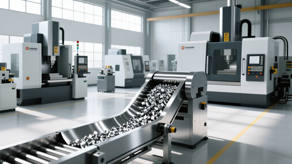
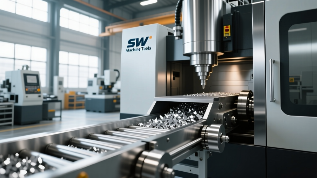
Selecting the correct chip conveyor for SW machine tools requires matching the conveyor mechanics to the specific shear plane and chip morphology of the workpiece material. According to Modern Machine Shop, mismatching conveyor type to chip shape is the leading cause of premature drive motor failure and belt jamming.
| Conveyor Type | Optimal Material / Chip Type | Speed & Torque Specs | Limitations in SW Centers |
|---|---|---|---|
| Hinge Belt (Slat) | Cast iron, brittle aluminum (AlSi9Cu3), short C-shaped chips | 10-20 ft/min; high tensile strength | Fails with long, stringy steel chips; wire-like chips wrap around drive shafts. |
| Scraper / Auger | Steel alloys, titanium, stringy/bird-nest chips | 5-15 ft/min; high torque, low speed | Poor coolant drainage; fine aluminum powders can jam the auger flights. |
| Drag Chain / Scraper Belt | Mixed materials, fine sludge, high-volume aluminum | Variable; excellent for submerged troughs | Higher initial capital cost; requires strict tension maintenance. |
Coolant Filtration and Thermal Stability
Evacuating the chip from the machine envelope is only half the battle; separating the micron-level particulate from the coolant is critical for maintaining the thermal stability and surface finish capabilities of SW machining centers. High-pressure through-spindle coolant (TSC) systems operating at 70 to 120 bar require ultra-clean fluid to prevent rotary union seal degradation.
For high-volume SW lines, standard 50-micron drum filters are insufficient. Shops are increasingly adopting vacuum filtration systems capable of holding a consistent 15 to 20-micron clarity rating at flow rates exceeding 200 GPM. By maintaining coolant temperature within ±0.5°C (via integrated heat exchangers) and removing abrasive fines, the machine's linear scales and ball screws are protected from thermal expansion and particulate ingress.
Engineering Insight: 'In twin-spindle horizontal machining, a 2°C rise in coolant temperature due to poor filtration and heat extraction can induce a 12-micron thermal growth in the Z-axis. When holding bore tolerances of ±8 microns on transmission valve bodies, the filtration system is just as critical as the spindle bearings.' — Senior Applications Engineer, Automotive Powertrain Machining
Edge Cases and Real-World Failure Modes
Even with OEM-specified conveyor systems, SW machine tools operating in 24/7 Tier-1 automotive environments experience specific, non-obvious failure modes. Understanding these edge cases prevents unplanned downtime.
- Hydraulic Lock in the Trough: When machining highly porous powder metal components, the coolant becomes saturated with fine metallic sludge. If the conveyor's dwell time (the time the belt sits in the trough before inclining) is too short, the sludge does not settle, and the conveyor carries high-density fluid up the incline. This causes hydraulic lock, tripling the amp draw on the conveyor drive motor and eventually shearing the torque limiter pin.
- Capillary Action Carryover: Hinge belt conveyors rely on wiper blades to strip coolant from the belt before discharging chips into the bin. When using semi-synthetic coolants with high surfactant concentrations, capillary action pulls coolant past the wiper. Over a 3-shift weekend run, this can result in the loss of 50+ gallons of coolant and a dangerously low sump level by Monday morning.
- Stringer Wrapping on the Head Pulley: When switching from aluminum to 4140 steel without changing the conveyor speed parameters, long stringers wrap around the head pulley. As the layers build up, the belt tracking shifts laterally, causing the belt edge to slice against the conveyor frame, resulting in a $4,500 belt replacement and 4 hours of downtime.
Maintenance Economics and Downtime Mitigation
The financial impact of swarf management failure on an SW machining line is severe. A single BA W06 twin-spindle machine generating $150 per hour in gross margin will cost the shop $1,200 in lost production during a 4-hour conveyor teardown. To mitigate this, maintenance teams must shift from reactive fixes to predictive component swapping.
Actionable Maintenance Framework
Implement the following interval-based maintenance schedule for SW machine tool chip conveyors:
- Weekly (Shift 1 PM): Inspect torque limiter clutch settings. Verify the slip torque is set exactly 15% above the steady-state running torque. If set too high, a jam will burn out the VFD (Variable Frequency Drive) instead of slipping the clutch.
- Monthly: Measure hinge belt elongation. A standard 1-inch pitch steel belt should not exceed 1.5% elongation over a 10-foot span. Adjust take-up bearings accordingly. If elongation exceeds 2.5%, schedule a belt replacement during the next planned outage.
- Bi-Annually: Replace the conveyor wiper blade and inspect the incline wear strips. UHMW (Ultra-High Molecular Weight) polyethylene wear strips should be swapped when the groove depth exceeds 1/8 inch to prevent belt derailment.
By treating the chip conveyor and filtration system as a precision subsystem rather than a disposal mechanism, shops running SW machine tools can protect their capital investment, maintain tight geometric tolerances, and eliminate the hidden costs of swarf-induced downtime.