Smart Machine Tool Spindles: Vibration & Rigidity Analysis
Discover how smart machine tool spindles leverage integrated sensors, active damping, and digital twins for real-time vibration analysis and dynamic rigidity.
The Shift from Static to Dynamic Rigidity Metrics
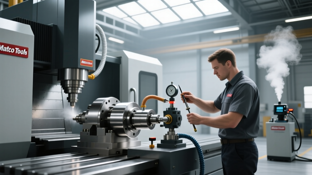
For decades, machine tool builders marketed rigidity as a single, static number—typically measured in Newtons per micrometer (N/µm) at the spindle nose. While a static rigidity of 250 N/µm on an HSK-A63 interface might look impressive on a brochure, it tells a machinist almost nothing about how the machine will behave when a 12-flute carbide endmill engages Titanium Ti-6Al-4V at 12,000 RPM. As of 2026, the industry standard for evaluating machine tool spindles has decisively shifted from static stiffness to dynamic compliance and real-time vibration analysis.
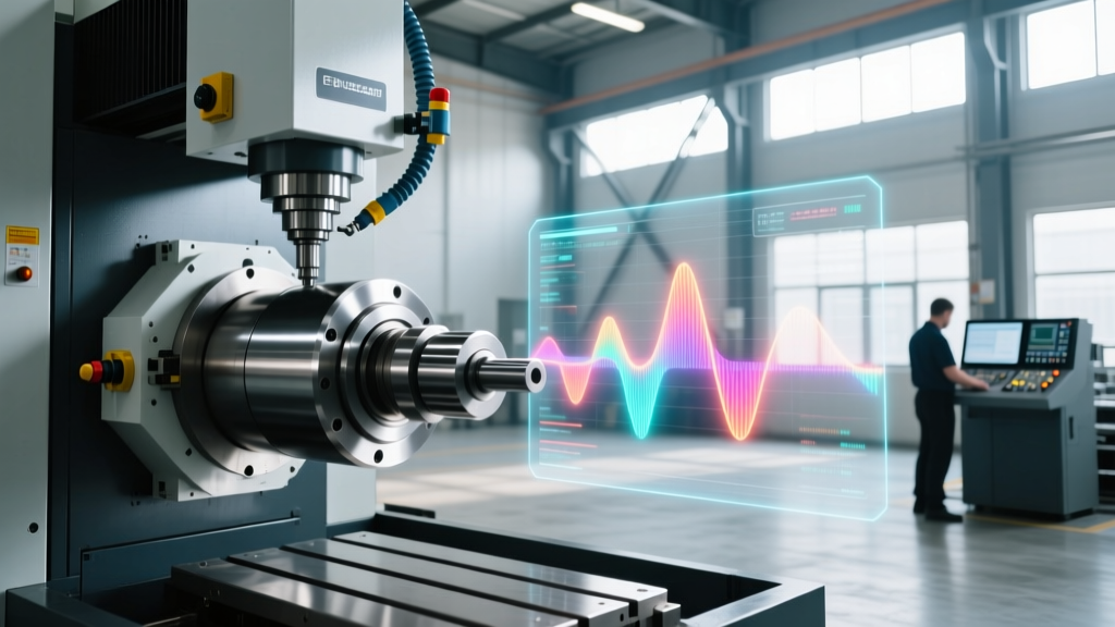
Dynamic rigidity measures the spindle's resistance to deflection under oscillating cutting forces at specific frequencies. Structural modes typically occur between 100 Hz and 800 Hz, while spindle shaft and tooling modes can resonate between 1,500 Hz and 5,000 Hz. When cutting forces align with these natural frequencies, regenerative chatter occurs, destroying surface finish and accelerating bearing wear. Modern smart spindles now address this through embedded sensor arrays and closed-loop active damping systems.
Key Distinction: Static vs. Dynamic DeflectionStatic Deflection: A constant 1,000 N radial force applied to a stationary spindle nose causing a 4 µm offset.
Dynamic Deflection: A 1,000 N oscillating radial force at 450 Hz causing a 22 µm offset due to structural resonance amplification. Dynamic analysis is the only reliable predictor of chatter limits.
Integrated Sensor Topologies for Vibration Analysis
Retrofitting external accelerometers to a spindle housing is no longer sufficient for high-precision aerospace and medical machining. The latest generation of smart machine tool spindles features internally embedded sensor arrays positioned directly behind the front bearing pack. This placement minimizes signal attenuation and provides a true representation of tool-point dynamics.
Piezoelectric vs. MEMS vs. Eddy Current Probes
Choosing the right sensor topology depends on the specific vibration signature you need to capture. While MEMS (Micro-Electromechanical Systems) accelerometers have improved significantly, high-end spindle manufacturers like Kessler and GMN still rely on piezoelectric sensors for high-frequency chatter detection, alongside eddy current probes for non-contact displacement measurement.
| Sensor Type | Frequency Range | Measurement Axis | Approx. Integration Cost | Best Application |
|---|---|---|---|---|
| ICP Piezoelectric (e.g., PCB 352C33) | 0.5 Hz to 10,000 Hz | Triaxial | $1,200 - $2,500 | High-frequency chatter & bearing defect detection |
| Industrial MEMS Accelerometer | DC to 3,000 Hz | Triaxial | $300 - $600 | General machine health & low-frequency structural vibration |
| Eddy Current Displacement Probe | 0 Hz to 5,000 Hz | Radial / Axial | $2,800 - $4,500 | Thermal growth tracking & precise spindle nose deflection |
To accurately capture a 2,500 Hz chatter frequency, the Nyquist-Shannon sampling theorem dictates a minimum sampling rate of 5,000 Hz. However, to resolve the waveform shape and calculate accurate RMS values for CNC controller integration, modern data acquisition systems in smart spindles sample at 25 kHz to 50 kHz. According to research from the UBC Manufacturing Automation Laboratory, high-speed sampling combined with operational modal analysis (OMA) is critical for updating stability lobe diagrams on the fly without interrupting production.
Active Damping and Real-Time Chatter Suppression
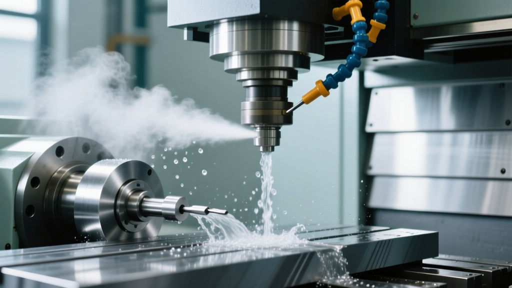
Passive damping—such as filling machine columns with polymer concrete or using tuned mass dampers inside the spindle shaft—only addresses known, fixed resonant frequencies. In 2026, the frontier of spindle technology is active magnetic and piezoelectric damping.
Active damping systems utilize the embedded sensor array to detect the onset of regenerative chatter within milliseconds. The controller then sends an out-of-phase counter-signal to piezoelectric actuators mounted in the spindle housing. These actuators physically push against the spindle shaft, effectively increasing the dynamic stiffness at the exact resonant frequency where chatter is occurring.
'The integration of active piezoelectric damping in HSK-100 and Capto C8 spindles allows heavy-duty roughing of Inconel to proceed at axial depths of cut that would previously trigger catastrophic chatter. We are seeing dynamic stiffness improvements of up to 400% at targeted structural modes.' — Dr. Yusuf Altintas, Manufacturing Automation Laboratory.
The Cost of Active Damping Systems
Upgrading from a standard high-frequency spindle to an active-damping smart spindle typically adds between $28,000 and $45,000 to the base price of a 5-axis machining center. For job shops running high-mix, low-volume parts where manual chatter tuning (adjusting RPMs by ear) wastes hours of setup time, this premium is quickly recovered through increased material removal rates (MRR) and reduced scrap.
Digital Twins and Predictive Vibration Modeling
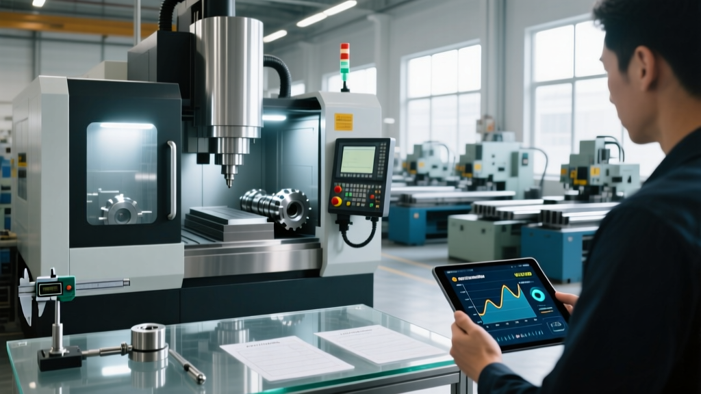
Hardware innovation in machine tool spindles is only half the equation; the software interpreting the vibration data is where the true information gain occurs. Leading CNC manufacturers are now integrating spindle digital twins directly into the machine control. A digital twin is a real-time virtual model of the spindle-tool-holder-cutting tool assembly that calculates the Frequency Response Function (FRF) at the tool tip.
Implementing a predictive spindle digital twin requires a structured calibration process. Below is the standard workflow utilized by advanced manufacturing facilities:
- Baseline Tap Testing: Perform an impact hammer test on the empty spindle nose and the loaded toolholder to establish the baseline FRF and identify the first three bending modes.
- Spindle Speed Variation (SSV) Mapping: Run a semi-finishing pass while the controller automatically varies the spindle speed by ±2% to disrupt the regenerative chatter phase, allowing the software to map the stability boundaries.
- Real-Time OMA Integration: During production, the embedded accelerometers perform Operational Modal Analysis, continuously updating the digital twin's FRF as the spindle bearings thermally expand and alter the preload.
- Automated Feed Override: If the digital twin predicts an impending stability lobe crossing due to tool wear altering the cutting force coefficients, the CNC automatically scales the feed rate down by 15% to maintain a stable cut until the tool is changed.
This level of integration is heavily supported by advanced manufacturing initiatives. The NIST Advanced Manufacturing Program has published extensive frameworks on how digital twins and real-time sensor data can reduce machine downtime and improve part geometry in multi-axis milling.
Strategic Implementation: When to Invest in Smart Spindles
Not every machine shop needs a $60,000 smart spindle with active damping and embedded eddy current probes. The decision to invest should be driven by the specific failure modes and bottlenecks in your current production environment.
High-Value Use Cases
- Aerospace Structural Milling: Machining deep, thin-walled pockets in 7075-T6 aluminum. The walls change dynamic stiffness as material is removed, requiring real-time stability lobe updates to avoid chatter and scrapped monolithic structures.
- Hard Metal Die & Mold: Finish milling H13 tool steel at 52 HRC. Spindle vibration analysis detects micro-chipping on the CBN or carbide tool edges before catastrophic failure occurs, saving $800+ per tool and preventing workpiece ruin.
- High-Speed Micro-Machining: Utilizing 40,000+ RPM spindles for medical implants. At these speeds, even a 1 µm imbalance causes severe bearing degradation. Embedded sensors trigger automated balancing cycles before bearing fatigue sets in.
When Standard Spindles Suffice
If your shop primarily performs 2.5D prismatic milling in mild steels or aluminum, or if your cycle times are under 3 minutes with frequent tool changes, the ROI on a smart spindle is difficult to justify. In these scenarios, investing in high-quality toolholding (such as hydraulic or shrink-fit chucks to maximize the static rigidity of the tool-spindle interface) and utilizing the Sandvik Coromant machining knowledge base to optimize cutting parameters will yield a better return on capital.
Ultimately, the transition from passive mechanical components to intelligent, data-generating assets is redefining machine tool spindles. By understanding the nuances of dynamic rigidity, selecting the correct sensor topology, and leveraging digital twin software, manufacturers can push cutting parameters to their absolute physical limits while maintaining flawless surface finishes and maximizing spindle bearing life.