Maintaining Safety Interlocks and E-Stops on Advanced Technology Machine Tools
Master the maintenance schedules for safety interlocks and E-stops on technology machine tools. Learn testing protocols, failure modes, and upgrade paths.
The Evolution of Safety Circuits in Technology Machine Tools
Modern technology machine tools—ranging from 5-axis CNC machining centers to automated wire EDMs and laser cutting cells—rely on complex safety matrices to protect operators from high-velocity spindles, toxic coolant mist, and intense thermal radiation. Unlike legacy manual mills that utilized simple electromechanical contactors, today's equipment integrates solid-state safety relays, RFID-coded door switches, and IO-Link Safety protocols. Maintaining these systems requires a shift from reactive part-swapping to proactive, data-driven lifecycle management.
According to OSHA's Machine Guarding guidelines, the failure of an interlock or emergency stop (E-stop) circuit is a primary contributor to severe amputation and crushing injuries in manufacturing environments. As of 2026, the integration of smart sensors allows maintenance teams to monitor the exact actuation cycles of safety components, predicting failures before they compromise the machine's Performance Level (PL).
Mandatory Maintenance Schedules for Safety Components
A robust maintenance program for technology machine tools must align with ISO 13849-1 standards, categorizing safety functions by their required reliability. Below is the engineered service schedule for E-stops and door interlocks.
Daily: Operator Functional Verification
- E-Stop Actuation: Operators must physically press and twist-release every E-stop button during the morning startup sequence. The machine's HMI must display a specific safety fault code (e.g., Siemens S7-1500 F-DB block fault), confirming the PLC registered the signal, not just a localized contactor drop.
- Door Interlock Check: Open and close all primary access doors. Verify that the spindle brake engages within the manufacturer's specified stopping time (typically under 1.5 seconds for high-inertia spindles) before the door latch releases.
Weekly: Electrical Integrity Testing
- Voltage Drop Measurement: Maintenance technicians should measure the voltage drop across E-stop contact blocks using a digital multimeter (e.g., Fluke 87V) in the millivolt range. A drop exceeding 50mV under load indicates internal contact degradation or oxidation.
- Actuator Alignment: Inspect the gap between door-mounted actuators and switch bodies. For RFID switches like the Schmersal AZM40, the alignment tolerance is strictly ±2mm. Misalignment causes intermittent reads, leading to nuisance machine faults.
Monthly: Mechanical and Environmental Inspection
- Coolant Ingress Check: Technology machine tools generate high-pressure coolant mist. Inspect the IP67-rated seals on all interlock switches. Look for capillary wicking of fluid into the wiring conduit, which can short 24VDC safety circuits.
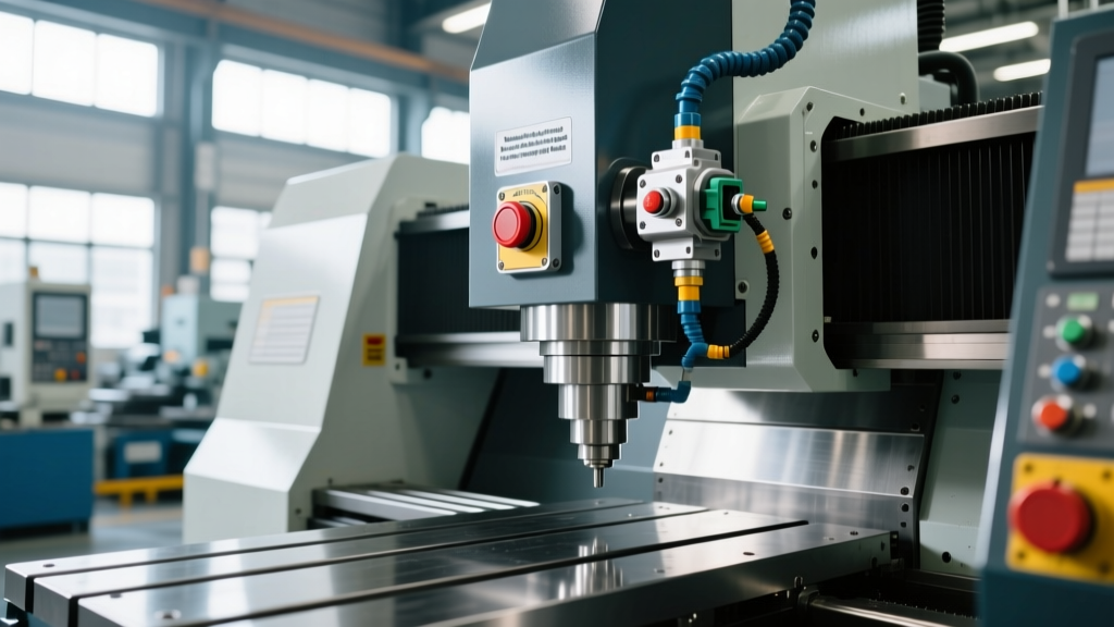
- E-Stop Button Mechanics: Verify the positive-break mechanism of the E-stop button. The button must remain physically locked in the depressed position until manually twisted or pulled to release.
Annually: Safety Logic and Lifecycle Validation
Conduct a full validation of the safety PLC logic. This includes injecting simulated faults into dual-channel circuits to ensure cross-fault detection is active. Calculate the remaining B10d lifecycle of electromechanical relays based on the machine's actual actuation logs extracted from the CNC controller.
CRITICAL WARNING: Defeated InterlocksNever bypass an interlock using zip-ties, tape, or spare actuators taped to the machine frame. Modern RFID interlocks utilize coded actuators with up to 4 billion unique codes. If a machine requires frequent interlock overrides for setup, the safety logic must be reprogrammed to include a dedicated, key-switch-activated 'Setup Mode' that restricts spindle speed to under 250 RPM, complying with OSHA 1910.212 General Machine Requirements.
Step-by-Step E-Stop Functional Testing Protocol
When validating an E-stop circuit on a technology machine tool, simply observing that the machine stops is insufficient. You must verify the dual-channel redundancy. Follow this exact sequence:
- Isolate the Drive: Ensure the main spindle drive is enabled and rotating at a low RPM (e.g., 500 RPM) in MDI mode.
- Actuate the E-Stop: Depress the E-stop button. Verify immediate cessation of spindle movement and the dropping of the main contactor.
- Verify Dual-Channel Faulting: Access the safety relay diagnostic LEDs (e.g., on a Pilz PNOZmulti 2 base unit). Both Channel 1 (CH1) and Channel 2 (CH2) LEDs must extinguish simultaneously. If one channel drops significantly later than the other, the safety relay will lock out, indicating a wiring fault or welded contact.
- Measure Contact Resistance: With the machine locked out and tagged out (LOTO), disconnect the E-stop wiring. Measure the resistance across the normally closed (NC) contacts. It must read less than 0.5 ohms. Anything higher requires immediate replacement of the contact block.
- Reset and Clear: Twist to release the E-stop. Reset the safety relay. Verify that the machine requires a deliberate secondary action (such as pressing a physical 'Reset' button on the operator panel) before the drive can be re-enabled. This prevents automatic, unexpected restarts.
Component Lifespan, B10d Values, and Replacement Costs
Understanding the B10d value—the number of cycles until 10% of a batch of components fail—is critical for scheduling preventative replacements on technology machine tools. Below is a matrix of standard safety components used in modern CNC and fabrication equipment.
| Component Type | Model Example | B10d Cycles | IP Rating | Est. Replacement Cost (2026) |
|---|---|---|---|---|
| RFID Door Interlock | Schmersal AZM40 | 1,000,000 | IP67 | $320 - $380 |
| E-Stop Contact Block | Siemens 3SU1150 | 2,000,000 | IP65 | $45 - $65 |
| Configurable Safety Relay | Pilz PNOZmulti 2 | N/A (Solid State) | IP20 (Panel) | $850 - $1,100 |
| Hinge Safety Switch | Euchner TZ3 | 500,000 | IP67 | $250 - $300 |
Troubleshooting Common Interlock Failures
When a technology machine tool throws a safety fault, the root cause is rarely the PLC logic itself. It is almost always a physical degradation at the sensor or actuator level.
Failure Mode 1: Coolant-Induced Short Circuits
Symptom: The machine randomly faults with a 'Door Open' error during high-pressure coolant cycles, but resets when the coolant stops.
Root Cause: Micro-fractures in the polyurethane cable jacket allow water-based coolant to wick into the safety relay inputs, altering the resistance and tricking the dual-channel monitoring into detecting a cross-fault.
Fix: Replace the switch and upgrade the cabling to IP69K-rated M12 connectors with integrated molded strain reliefs. Apply dielectric grease to the connector threads.
Failure Mode 2: Actuator Mechanical Wear
Symptom: The interlock fails to engage consistently when the heavy polycarbonate door is closed, requiring the operator to slam the door.
Root Cause: The mechanical tongue of a legacy switch (like an Allen-Bradley 440G-TZ) has worn down, or the door hinges have sagged by 3mm, pushing the actuator out of the switch's capture zone.
Fix: Realign the door hinges. If the switch tongue shows visible grooving, replace both the switch and the actuator. Consider upgrading to a non-contact RFID switch to eliminate mechanical wear entirely.
Upgrading to IO-Link Safety for Predictive Maintenance
For facility managers overseeing fleets of technology machine tools, retrofitting legacy hardwired safety circuits with IO-Link Safety is the most impactful upgrade available in 2026. IO-Link Safety transmits standard safety signals (F-Device) over standard, unshielded M12 cables, while simultaneously providing rich diagnostic data.
With IO-Link, the CNC controller can read the exact temperature of the safety relay, the number of actuations, and the signal quality of RFID interlocks. This allows maintenance software to trigger a work order when an E-stop button reaches 80% of its B10d lifecycle, or when a door switch's internal temperature rises due to a failing voltage regulator, completely eliminating unplanned safety-related downtime.