US Machine Tool Lubrication Systems: Specs and Schedules
Explore the technical specifications and maintenance schedules for US machine tool lubrication systems to maximize CNC spindle and way lifespan.
The Architecture of US Machine Tool Lubrication Systems
Modern CNC manufacturing relies on precision tribology to maintain micron-level tolerances. In the US machine tool market, original equipment manufacturers (OEMs) like Haas, Hurco, and DMG MORI deploy highly specific centralized lubrication architectures designed to manage extreme shear forces, thermal expansion, and way stick-slip. Understanding the technical specifications of these systems is mandatory for maintenance engineers aiming to prevent catastrophic spindle failures and axis drive faults.
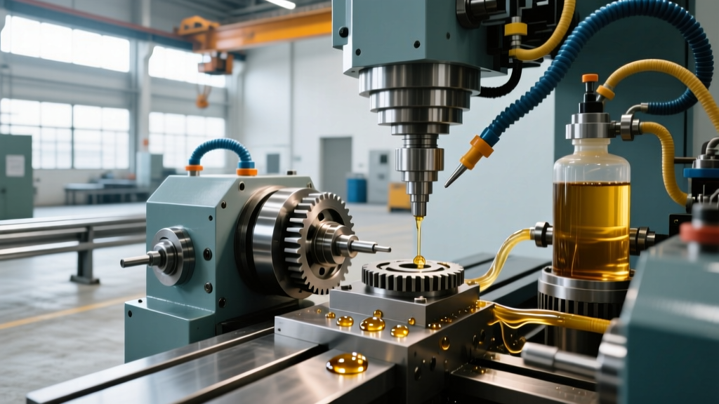
Unlike manual grease fittings or splash lubrication, centralized automated systems meter exact volumetric doses of lubricant to dozens of distribution points simultaneously. The dominant architectures found in US-manufactured or US-distributed CNC equipment fall into three distinct categories: Single-Line Resistance (SLR), Single-Line Parallel (SLP/Volumetric), and Progressive Metering.
System Architecture Comparison Matrix
| System Type | Operating Pressure | Metering Mechanism | Primary CNC Application | Failure Mode Characteristic |
|---|---|---|---|---|
| Single-Line Resistance (SLR) | 100 - 300 PSI | Restrictors / Orifices | Light-duty mills, lathes | Uneven distribution if lines restrict |
| Single-Line Parallel (SLP) | 300 - 800 PSI | Positive Displacement Injectors (PDI) | Vertical Machining Centers (VMCs) | Individual injector spring failure |
| Progressive Metering | 1,000 - 3,000 PSI | Series-linked spool valves | Heavy gantry mills, boring mills | Single blockage halts entire system |
Fluid Dynamics: Viscosity and Tackifier Chemistry
The physical properties of the lubricant dictate the mechanical design of the pump and metering units. US machine tool builders overwhelmingly specify ISO Viscosity Grade (VG) 68 for slideway applications, with Mobil Vactra Oil No. 2 or Castrol Magna BD 68 serving as the baseline reference fluids.
Tribology Note: Standard hydraulic or motor oils lack the necessary 'tackifiers' (typically high-molecular-weight polyisobutylene polymers) required for way lubrication. Without these polymers, centrifugal forces from rapid axis traverses (exceeding 1,000 ipm on modern linear-drive machines) will throw the oil off the vertical columns, leading to dry sliding and immediate way scoring.Combating the Stick-Slip Phenomenon
When a heavy CNC table transitions from a static state to dynamic motion on cast-iron or Turcite-coated ways, static friction exceeds kinetic friction. This differential causes 'stick-slip'—a micro-stuttering effect that destroys surface finish accuracy during contouring. To neutralize this, US-spec way lubes incorporate specific friction modifiers, such as zinc dialkyldithiophosphate (ZDDP) and fatty acid esters. These additives chemically bond to the metallic way surfaces, creating a boundary layer that equalizes the static-to-kinetic friction coefficient, ensuring smooth interpolation at feed rates as low as 0.1 inches per minute.
Internal Mechanics of Positive Displacement Injectors (PDIs)
The heart of the SLP volumetric systems favored by major US CNC brands is the Positive Displacement Injector (PDI). Manufactured by industry leaders like Bijur Delimon and SKF Lincoln, these components are marvels of micro-fluidic engineering. For a deeper understanding of single-line parallel system architectures, engineers must look at the internal valving sequence.
- Pressurization Phase: The central pump pressurizes the main supply line to 450 PSI. Fluid pressure overcomes the internal return spring of the PDI, forcing the piston downward.
- Discharge Phase: As the piston moves, it opens a check valve and forces a precise volume of oil (typically calibrated between 0.01 and 0.16 cubic inches) out to the local distribution block.
- Venting Phase: The pump shuts off, and a system vent valve depressurizes the main line. The internal spring pushes the piston back to its resting position, drawing fresh fluid from the main line into the injector chamber for the next cycle.
If the main line does not fully vent to zero pressure, the PDI cannot reset. This is a common root cause of 'Lube Pressure High' or 'Cycle Incomplete' alarms on CNC controllers.
OEM Maintenance Schedules and Telemetry
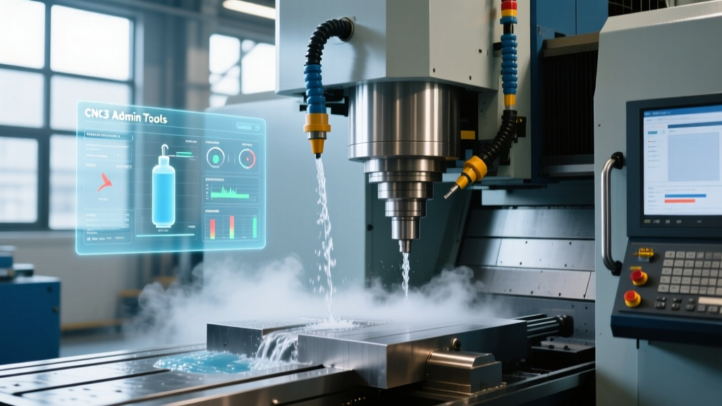
Adhering to strict maintenance intervals is non-negotiable. While older machines relied on physical logbooks, the 2026 standard for US machine tool environments involves MTConnect integration, where pump cycle counts and pressure decay rates are streamed directly to shop-floor dashboards for predictive maintenance.
Required Maintenance Intervals
- Daily (8-Hour Shift): Verify physical reservoir level. Check for localized pooling of oil at axis limits (indicates way wiper seal failure or localized over-lubrication).
- 500-Hour Interval: Inspect the primary suction strainer inside the reservoir. Clean with solvent to remove polymerized oil varnish. Verify pressure switch actuation by manually triggering a lube cycle and observing the gauge spike and subsequent decay.
- 2,000-Hour Interval: Flush the entire reservoir and distribution network. Over time, way lube degrades and forms sludge that clogs the micro-orifices of SLR restrictors and PDI check valves. Refill with fresh ISO VG 68 fluid.
- Annual: Replace all flexible polyurethane distribution tubing. Coolant exposure causes these lines to embrittle and crack, leading to invisible leaks inside the sheet metal enclosures.
Troubleshooting Common CNC Lube Alarms
When a CNC controller halts operation due to a lubrication fault, rapid diagnosis is required to minimize downtime. Below is a technical decision tree for the most frequent alarms encountered on US-market controllers.
Alarm: 'Lube Pressure Low' (e.g., Haas Alarm 1014)
- Cause A: Reservoir empty or suction strainer clogged.
Fix: Refill tank, clean strainer, prime pump. - Cause B: Major line rupture or disconnected fitting.
Fix: Inspect flexible lines near axis flex-points. Replace cracked polyurethane tubing with 1/4" OD rated lines. - Cause C: Pump relief valve stuck open.
Fix: Disassemble pump head, clean relief valve seat of debris, reset spring tension to 450 PSI.
Alarm: 'Lube Cycle Incomplete' / 'Timeout'
- Cause A: System failing to vent (pressure trapped in lines).
Fix: Check the vent valve on the pump manifold. If the vent valve solenoid is burnt out or the spool is varnished, the PDI injectors cannot reset for the next cycle. - Cause B: Seized PDI injector.
Fix: Isolate zones by capping distribution blocks. Trigger manual cycles to identify the zone failing to build pressure, then replace the seized PDI unit.
For comprehensive insights into managing slideway friction and preventing boundary lubrication failures, maintenance teams should regularly consult industry guidelines on slideway lubrication principles. Proper calibration of these systems ensures that the machine tool maintains its geometric accuracy over decades of heavy metal removal.
Summary of Critical Specifications
- Standard Fluid: ISO VG 68 Way Lubricant (with tackifiers and anti-stick-slip modifiers).
- Standard Pump Pressure: 400 - 500 PSI for SLP/Volumetric systems.
- Injection Volume: 0.01 to 0.16 cubic inches per PDI cycle.
- Cycle Frequency: Typically 15 seconds of pump-on time per 15 to 30 minutes of machine operation (adjustable via CNC parameters).
- Tubing Spec: 1/8" to 1/4" OD Polyurethane, rated for minimum 800 PSI burst pressure.