Mastering Machine Tool Technology: DRO and Control System Training
Train operators on modern machine tool technology. Master DRO readouts, CNC control pre-flight checks, and linear scale maintenance to reduce scrap.
The Shift to Advanced Machine Tool Technology on the Shop Floor
Scrap rates in modern job shops rarely stem from a lack of mechanical aptitude; they trace back to a fundamental misunderstanding of digital interfaces. As manual mills and lathes are retrofitted or replaced, operators must transition from relying on tactile handwheel feedback to interpreting digital data. Mastering modern machine tool technology—specifically Digital Read Out (DRO) systems and hybrid CNC control panels—requires retraining muscle memory and spatial reasoning. An operator who treats a DRO like a simple digital dial indicator will inevitably crash the machine or scrap the part when dealing with thermal growth, backlash, or complex geometric arrays.
Effective operator training must move beyond basic X-Y-Z coordinate reading. It requires a deep understanding of absolute versus incremental positioning, tool radius compensation, and the physical maintenance of the linear scales that feed data to the readout. According to workforce development data from the NIST Manufacturing Extension Partnership, shops that implement structured, technology-specific training protocols see a 22% reduction in first-part scrap rates compared to those relying on informal peer-to-peer shadowing.
Mastering DRO Readouts: Beyond Basic Coordinate Tracking
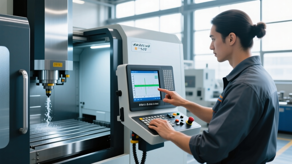
Current-generation DROs, such as the Heidenhain ND 780 or the Newall E70, are essentially standalone geometric calculators. Operators must be trained to utilize these computational features to eliminate manual layout errors and reduce setup times. The most critical conceptual hurdle for new operators is the distinction between Absolute (ABS) and Incremental (INC) modes, and the catastrophic results of mixing them up mid-operation.
Shop Floor Warning: The Incremental TrapNever allow an operator to use Incremental (INC) mode for multi-step operations without a strict zeroing protocol between steps. If an operator bumps the table or loses position in INC mode, the DRO has no reference to the part datum. Always mandate Absolute (ABS) mode for primary part datums, reserving INC mode strictly for single-feature depth calls or temporary tool clearance checks.
Advanced DRO Functions and Shop Floor Applications
Training must include practical exercises on the following computational features, which are standard on modern machine tool technology interfaces:
| DRO Function | Mathematical Basis | Best Practice Application |
|---|---|---|
| Bolt Hole Circle | Polar to Cartesian coordinate conversion based on center point, radius, and hole count. | Flange drilling. Train operators to set the X-Y center datum first, then input the pitch circle diameter (PCD) and start angle to eliminate manual rotary table indexing. |
| Line Hole Pattern | Linear interpolation calculating equal divisions along a defined vector. | Drilling linear arrays on an angle. Operators input the start point, end point, and number of holes, allowing the DRO to calculate the exact X-Y drop for each station. |
| Tool Offset / Radius Comp | Vector shifting based on cutter diameter and climb/conventional milling direction. | Profile milling. Operators must input the exact measured tool diameter (not the nominal size) to hold tight tolerances on manual contouring passes. |
| Skew Compensation | Angular axis rotation to align the DRO coordinate system with a misaligned part. | Secondary operations on castings or weldments. Probe two points on an irregular edge, and the DRO mathematically squares the part in software, eliminating the need to physically re-indicate the vise. |
Control System Pre-Flight Protocols
When operators transition from manual DRO mills to full CNC systems (like the FANUC 0i-F Plus or Haas Next Gen control), the physical disconnect from the cutting tool increases the risk of high-speed crashes. Machine tool technology provides robust safety nets, but only if the operator engages them. Training must enforce a rigid 'Pre-Flight' protocol before the first Cycle Start is ever pressed.
'A CNC machine will do exactly what you tell it to do, not what you meant for it to do. The distance between a typo and a $15,000 spindle rebuild is bridged entirely by the Single Block and Feedrate Override switches.' — Senior Manufacturing Engineer, SME Technical Council
The 5-Step Dry Run Execution Flow
Operators must memorize and execute this sequence for every new program or offset change:
- Z-Axis Shift: Raise the work coordinate system (WCS) Z-datum by +2.000 inches (or +50mm) in the control offsets. This creates a physical buffer zone above the part.
- Engage Single Block: Flip the Single Block switch to ON. This forces the control to pause at the end of every single line of G-code, preventing rapid sequential movements.
- Cap the Feedrate: Turn the Feedrate Override dial down to 10% or 25%. Rapid traverse (G00) moves will still occur at full speed, but cutting moves (G01/G02/G03) will be slow enough to visually verify.
- Monitor Distance to Go: Train operators to keep their eyes on the 'Distance to Go' screen, not just the absolute position. The machine should stop exactly when the 'Distance to Go' reads zero.
- Gradual Release: After verifying the first three tool paths safely clear the part and fixtures, lower the Z-shift back to zero in increments of 0.500 inches, gradually increasing the Feedrate Override to 100%.
Hardware Care: Linear Scales and Readout Maintenance
Advanced machine tool technology is only as accurate as the data feeding it. DROs rely on linear scales mounted to the machine axes. Operators are often the first line of defense in maintaining these delicate components. A crashed machine or a poorly maintained scale will result in 'DRO drift'—where the digital readout no longer matches the physical table position.
Glass vs. Magnetic Scales: What Operators Need to Know
Most retrofitted manual machines use glass linear scales with a standard resolution of 5µm (0.0002 inches). These are housed in aluminum extrusions with rubber wipers. Newer, high-end installations often use magnetic scales, which offer 1µm (0.00005 inches) resolution and are completely immune to coolant intrusion.
Maintenance Directive: Cleaning Glass ScalesIf coolant breaches the glass scale housing, the scale must be cleaned immediately. Operators must use only 99% isopropyl alcohol and lint-free optical wipes. Never use acetone, brake cleaner, or WD-40. Harsh solvents will dissolve the optical grating bonding agent, ruining the scale and necessitating a $400 to $1,200 replacement per axis.
Operators should be trained to inspect the rubber wiper seals at the ends of the scale extrusions weekly. If the wipers are torn or hardened, coolant and metal fines will be dragged directly into the glass housing. Replacement wiper kits cost between $45 and $90 per axis and take less than 15 minutes to install—a fraction of the cost of replacing the read head or the scale itself.
FAQ: Troubleshooting DRO Drift and Control Lag
Why does my DRO readout jump or flicker when the table moves?
This is almost always caused by metal fines (swarf) accumulating on the glass scale or the optical read head. The microscopic lines on the glass scale (usually 50 lines per millimeter) act as a diffraction grating. If metal dust blocks the light path, the read head loses its positional reference and 'jumps' to find the next readable line. Power down the machine, open the scale housing, and clean the glass with isopropyl alcohol.
The DRO matches my dial indicator on the X-axis, but the Y-axis is consistently off by 0.002 inches after a direction change. Is the scale broken?
The scale is likely fine; you are experiencing mechanical backlash. The DRO reads the position of the table (via the scale), while the handwheel dial reads the position of the leadscrew. If the Y-axis gibs are loose or the leadscrew nut is worn, the table will lag behind the leadscrew when reversing direction. Tighten the Y-axis gib lock and adjust the backlash compensation parameters in the DRO settings to electronically mask the mechanical wear.
Aligning Safety with Technological Capability
Integrating advanced readouts and CNC interfaces drastically improves part quality and setup speed, but it introduces new hazard vectors. As noted in the OSHA standard 1910.212 for general machine guarding, the presence of automated or digitally controlled movement requires strict adherence to guarding protocols. Operators must be trained never to lean over the cutting zone to read a DRO screen while the spindle is engaged, and machine enclosures must remain interlocked and closed during automated cycles. True mastery of machine tool technology is achieved only when digital precision is matched by rigorous safety and maintenance discipline.