Machine Tool Cooling System Calibration for ISO Accuracy Standards
Master machine tool cooling system calibration to eliminate thermal deformation. Learn operator best practices for meeting ISO 230-2 accuracy standards.
The Thermal Deformation Problem in CNC Machining
In precision manufacturing, thermal deformation is the silent killer of geometric accuracy. Research indicates that thermal errors account for 50% to 75% of all geometric inaccuracies in CNC machining centers. When a machine's structural components expand or contract unevenly, the tool center point (TCP) shifts, rendering tight tolerances impossible. The primary defense against this is a properly calibrated machine tool cooling system. Without precise thermal management, even a $500,000 5-axis mill will fail to hold a ±5 µm positional tolerance.
Thermal Expansion Reality Check:Cast iron (DIN GG25), the standard material for machine bases and columns, has a coefficient of thermal expansion (CTE) of 10.4 µm/m/°C. If a 1.5-meter Z-axis column experiences a localized 2°C temperature gradient due to inadequate spindle cooling, it will elongate by 31.2 µm. This single thermal shift instantly destroys a standard ISO 230-2 positioning tolerance.
For operators and maintenance teams, treating the machine tool cooling system as a secondary utility rather than a critical metrology component is a fundamental error. Calibration of these systems must be directly mapped to international accuracy standards.
Mapping Cooling Subsystems to ISO Accuracy Standards
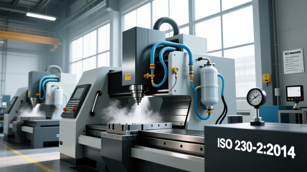
International standards dictate how machine tools are tested for accuracy under thermal load. The two most critical frameworks for thermal stability are ISO 230-2:2014 (Determination of accuracy and repeatability of positioning) and ISO 10791-1 (Test conditions for machining centres). To pass these certifications, specific cooling subsystems must maintain strict temperature deltas.
| Cooling Subsystem | Target Tolerance (ΔT) | Primary ISO Impact |
|---|---|---|
| Spindle Jacket Chiller | ±0.1°C (±0.18°F) | ISO 230-2 Z-axis repeatability & ISO 10791-1 thermal drift |
| Ball Screw Core Cooling | ±0.5°C (±0.9°F) | ISO 230-2 X/Y axis positioning accuracy |
| Flood Coolant (Cutting) | ±1.0°C (±1.8°F) | Workpiece dimensional stability (ISO 10791-7) |
| Motor / Drive Cabinet Cooling | ±2.0°C (±3.6°F) | Servo loop stability and encoder accuracy |
Step-by-Step Operator Calibration Protocol
Achieving the tolerances listed above requires moving beyond simple setpoint adjustments. Operators must execute a rigorous calibration protocol using traceable metrology equipment.
Phase 1: Sensor Verification and Baseline Mapping
Machine tool cooling systems rely on internal thermistors that degrade over time. Before adjusting the chiller, verify the actual fluid temperature at the delivery manifold.
- Equipment Required: Use a reference thermometer with an RTD probe, such as the Fluke 1523 with a 5615-9 probe (accuracy ±0.015°C).
- Measurement Point: Insert the probe into the test port immediately downstream of the chiller's supply pump, before the fluid enters the machine casting.
- Delta Calculation: Compare the Fluke reading to the chiller's digital HMI readout. If the variance exceeds 0.2°C, the chiller's internal sensor requires offset calibration via the manufacturer's service menu (e.g., Parker Hyperchill service mode).
Phase 2: Ambient-to-Setpoint Synchronization
A common operator mistake is setting the machine tool cooling system to a fixed 20°C (68°F) regardless of shop conditions. This causes condensation on cold machine surfaces in humid environments, or turns the machine casting into a heat sink in cold environments.
Operator Best Practice: Set the spindle chiller setpoint to match the ambient air temperature immediately surrounding the machine column, within ±1°C. If the shop is 23°C, set the chiller to 23°C. This achieves thermal neutrality, preventing the coolant from either extracting heat from or adding heat to the cast iron structure.Phase 3: The ISO 10791-1 Thermal Stability Run-In
Calibration is incomplete without verifying dynamic thermal stability under load. ISO 10791-1 requires a warm-up cycle to stabilize the machine. For high-speed spindles (12,000+ RPM), execute the following run-in:
- 0-30 Minutes: Spindle at 3,000 RPM, axes moving at 2,000 mm/min in a continuous 3D contour pattern.
- 30-60 Minutes: Spindle at 8,000 RPM, simulating heavy cutting loads.
- 60-90 Minutes: Spindle at maximum rated RPM (e.g., 15,000 RPM) for 15 minutes, followed by a 5-minute dwell.
Monitor the Z-axis thermal growth using a dial indicator or laser interferometer. If growth exceeds 10 µm during the final dwell phase, the chiller's PID controller loop is too slow, or the coolant flow rate is restricted.
Troubleshooting Common Thermal Drift Failure Modes
When a machine fails to hold tolerances during a mid-shift run, operators must quickly diagnose the machine tool cooling system. Below is a decision matrix for the most frequent thermal failure modes.
Symptom: Z-Axis Grows 15-25 µm After 4 Hours of Cutting
Root Cause: Spindle chiller refrigerant bypass or clogged inline filtration. As the spindle generates heat at high RPM, the chiller fails to extract it fast enough due to restricted flow.
Actionable Fix: Check the inline coolant filter. Spindle jackets require a 50-micron stainless steel mesh filter. If the pressure drop across the filter exceeds 0.3 bar (4.3 psi), replace it immediately. Next, check the chiller's sight glass for bubbles, indicating low refrigerant charge.
Symptom: X-Axis Positioning Inaccuracy (Cyclic Error)
Root Cause: Ball screw core cooling failure. The ball screw expands linearly as friction builds up, pushing the nut and altering the X-axis absolute position.
Actionable Fix: Verify the flow meter on the ball screw cooling circuit. Minimum flow should be 2.5 L/min. If flow is adequate but temperature delta is high, the rotary union on the ball screw is likely leaking internally, mixing the cooling oil with the way lube. Replace the rotary union seals.
Upgrading Legacy Chillers: ROI and Specifications
Many machines built prior to 2020 utilize standard on/off (bang-bang) immersion chillers. These systems cycle the compressor on and off, creating temperature swings of ±1.5°C. This is entirely incompatible with modern ISO 230-2 accuracy requirements for precision aerospace and medical machining.
Upgrading to an inverter-driven scroll compressor chiller (such as the Whaley Products VFD series or Parker Hyperchill Plus ICE models) provides proportional cooling. The compressor speed modulates continuously to match the exact heat load of the spindle, holding temperatures to ±0.1°C.
Financial Justification for Chiller Upgrades
- Capital Cost: $8,500 to $14,000 for a 3HP to 5HP inverter-driven chiller with integrated IoT monitoring.
- Scrap Reduction: Eliminating thermal drift on a 5-axis machine machining titanium aerospace structural parts (valued at $2,000+ per part) prevents an average of 2 scrapped parts per month.
- ROI Timeline: Typically 4 to 7 months based purely on scrap avoidance, excluding the value of eliminated manual compensation offsets.
According to metrology guidelines published by the National Institute of Standards and Technology (NIST), environmental and thermal factors are the dominant source of uncertainty in coordinate measuring machines and CNC tools alike. Controlling the thermal boundary condition via the cooling system is not optional for sub-10 µm work.
Daily Operator Maintenance Checklist
To maintain calibration between annual ISO certification audits, operators must integrate the machine tool cooling system into their daily startup routine. Relying solely on the maintenance department guarantees thermal drift will occur during production.
- Check Fluid Levels: Verify the chiller reservoir is at the 'MAX' line. Low fluid levels cause cavitation in the pump, leading to erratic flow and localized hot spots in the spindle jacket.
- Inspect Coolant Clarity: Spindle cooling oil (typically ISO VG 2 or VG 4) must be crystal clear. Milky oil indicates water ingress from a failed heat exchanger. Brown oil indicates oxidation and requires an immediate flush.
- Verify Flow Alarms: Intentionally pinch the return line for 3 seconds during startup to ensure the machine's PLC triggers a low-flow alarm and halts the spindle. A defeated or broken flow interlock is a catastrophic risk to the spindle bearings.
By treating the machine tool cooling system as a precision metrology instrument rather than a basic utility, shops can consistently achieve the tightest ISO accuracy standards, reduce scrap, and maximize the ROI of their capital equipment.
For further reading on cutting tool thermal dynamics and managing heat at the shear zone, refer to the Sandvik Coromant technical knowledge base, which provides extensive data on how workpiece material and cutting speeds interact with machine thermal stability.