Machining a Lewis Machine and Tool Bolt Carrier Group: Linear vs Box Ways
Explore how CNC machine tool way systems—linear guides vs. box ways—impact the precision machining of a Lewis Machine and Tool bolt carrier group.
The Tolerance Demands of a Lewis Machine and Tool Bolt Carrier Group
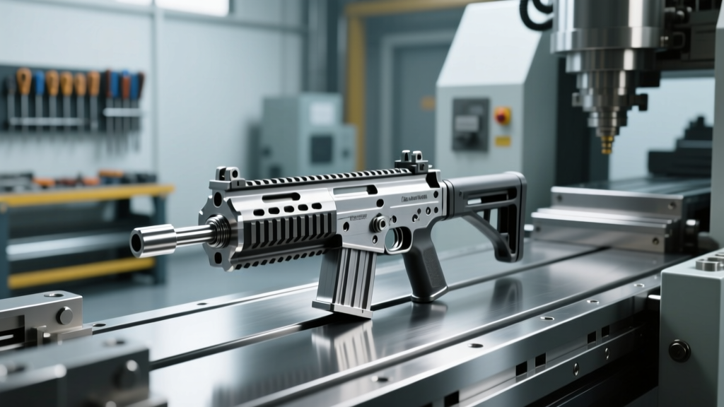
The manufacturing of a Lewis Machine and Tool bolt carrier group (BCG) represents one of the most demanding precision machining operations in the modern defense and commercial firearms sector. Unlike standard commercial BCGs that may rely on looser Mil-Spec tolerances to ensure interchangeability, LMT’s monolithic rail platforms and proprietary BCG designs require extreme geometric accuracy to maintain reliable cycling and lockup under adverse conditions.
The core carrier is typically machined from an 8620 alloy steel forging, while the bolt itself is crafted from 9310 vacuum-degassed steel. To achieve the necessary operational reliability, critical features such as the cam pin bore, the gas key interface, and the exterior bearing surfaces must be held to concentricity and dimensional tolerances of ±0.0002 inches. Achieving these micro-tolerances during high-volume production is not merely a function of tooling or CAM programming; it is fundamentally dictated by the structural dynamics of the CNC machine tool itself—specifically, the choice between linear guideways and traditional box ways.
Linear Guideways: High-Speed Precision for BCG Profiling
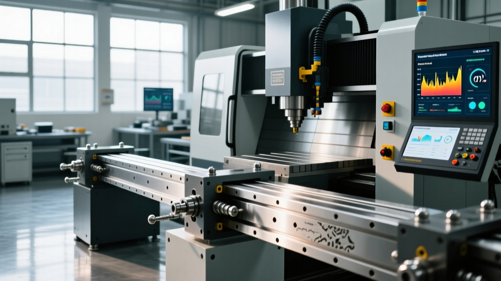
Linear guideways utilize recirculating ball or roller bearings that travel along precision-ground steel rails. This rolling-element design creates point or line contact between the bearing and the rail, resulting in an exceptionally low coefficient of friction (typically between 0.002 and 0.003). According to technical data from THK Linear Motion Systems, modern high-preload linear guides can sustain massive dynamic loads while maintaining nanometer-level positioning accuracy.
Application in BCG Manufacturing
When machining a Lewis Machine and Tool bolt carrier group, linear ways excel in operations requiring high rapid traverse rates and delicate finishing cuts:
- Exterior Profile Milling: Finish milling the bearing bands on the outside diameter (OD) of the 8620 carrier requires consistent feed rates without stick-slip. The near-zero static friction of linear guides ensures a flawless surface finish (often achieving Ra 16 µin or better) without the micro-stuttering associated with sliding friction.
- Cam Pin Slot and Bore Machining: The cam pin slot must be milled with extreme precision to ensure the bolt locks into battery at the exact rotational degree required. Linear ways provide the high-frequency responsiveness needed for simultaneous 3-axis contouring of this complex geometry.
- Drilling the Firing Pin Channel: Peck-drilling the deep, narrow firing pin channel through the length of the carrier requires high spindle speeds and rapid Z-axis retraction. Linear ways support Z-axis rapids exceeding 60 m/min, drastically reducing non-cutting cycle times.
While linear ways are inherently less rigid than box ways, modern CNC mills utilize "Heavy Preload" (often designated as Z0 or ZZ by manufacturers like Rexroth or THK) for firearm manufacturing. This preload eliminates internal clearance within the bearing blocks, artificially increasing the moment stiffness required to resist the radial cutting forces generated by carbide end mills profiling the 8620 steel.
Box Ways: Dampening Chatter in Deep Bore and Heavy Milling
Box ways represent the traditional sliding-contact method of machine tool axis movement. The male and female way surfaces are precision-scraped or ground to match, and the sliding surfaces are lined with a low-friction polymer composite, most commonly Turcite-B (a PTFE-based material). This creates a massive surface-area contact patch compared to the point contact of linear bearings.
The Physics of Vibration Dampening
The primary advantage of box ways in heavy manufacturing is vibration absorption. The sliding friction and the viscoelastic properties of the Turcite lining provide a damping coefficient up to 10 times greater than that of recirculating ball bearings. When roughing out the deep internal cavity of an LMT bolt carrier—which requires removing significant volumes of 8620 steel with large-diameter indexable drills or roughing end mills—regenerative chatter is the primary enemy of tool life and surface integrity.
According to Sandvik Coromant Metal Cutting Knowledge, chatter not only degrades the surface finish but causes micro-chipping on the cutting edges of carbide inserts. Box ways absorb the high-frequency harmonic vibrations generated during heavy interrupted cuts (such as milling across the gas key pin holes or the extractor slot), protecting the spindle bearings and extending tool life by up to 30% in heavy roughing applications.
Decision Matrix: Selecting the CNC Way System for BCG Production
For machine shops contracted to produce defense-grade components like the Lewis Machine and Tool bolt carrier group, selecting the right machine architecture is critical. Below is a technical comparison matrix evaluating both way systems across key manufacturing metrics.
| Performance Metric | Linear Guideways | Box Ways (Turcite-Lined) |
|---|---|---|
| Friction Coefficient | 0.002 - 0.003 (Rolling) | 0.04 - 0.06 (Sliding) |
| Vibration Damping | Low (Transmits to structure) | Exceptional (Absorbs harmonics) |
| Max Rapid Traverse | 48 - 60+ m/min | 15 - 24 m/min |
| Dynamic Load Capacity | High (with roller guides) | Extreme (Full surface contact) |
| Stick-Slip Tendency | None | Eliminated by PTFE liners |
| Ideal BCG Operation | Finish profiling, cam pin boring | Cavity roughing, heavy drilling |
Real-World Setup: Hybrid Cells and Tooling Dynamics
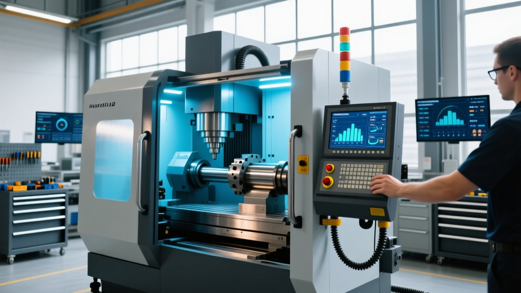
In a modern 2026 production environment, high-volume defense manufacturers rarely rely on a single machine type for the entirety of a complex component. Instead, shops utilize a hybrid cellular approach to machine a Lewis Machine and Tool bolt carrier group efficiently.
The Roughing Cell (Box Way VMCs)
The initial operations—facing the forging, roughing the main internal cavity, and drilling the primary gas ports—are assigned to heavy-duty Vertical Machining Centers (VMCs) equipped with box ways. These machines utilize high-torque, direct-drive spindles (often 12,000 RPM with 300+ ft-lbs of torque) and rigid tapping capabilities. The box ways absorb the massive shock loads generated when an indexable drill breaks through the far side of the 8620 steel cavity, preventing spindle bearing brinelling.
The Finishing Cell (Linear Way VMCs/HMCs)
Once the part is semi-finished and stress-relieved, it moves to a high-speed Horizontal Machining Center (HMC) or linear-way VMC. Here, the focus shifts to thermal stability and geometric precision. Linear ways generate significantly less friction heat than box ways, reducing the need for massive flood-coolant volume to manage axis-thermal growth. This thermal stability is crucial when boring the cam pin hole to its final ±0.0002-inch tolerance.
Warning: Coolant Pressure and Way ProtectionWhen machining the deep gas key channels and extractor slots of an LMT BCG, shops often employ 1,000 PSI through-spindle coolant to evacuate stringy 8620 steel chips. On box way machines, it is critical to ensure that the way covers (telescopic steel shields) are rated for high-pressure coolant impingement. If high-pressure coolant breaches the way covers, it will wash away the way lubricant and contaminate the Turcite lining, leading to rapid axis wear and catastrophic loss of positioning accuracy.
Tooling Synergy with Way Systems
The choice of way system also dictates the optimal cutting tool geometry. On linear-way machines, where high-speed contouring is the norm, variable-helix solid carbide end mills with AlTiN (Aluminum Titanium Nitride) coatings are preferred. These tools can run at surface speeds (SFM) of 450-550 in 8620 steel, leveraging the high feed rates of the linear guides. Conversely, on box-way roughing machines, shops utilize indexable helical milling cutters with thick, honed carbide inserts designed for high chip loads (0.008 to 0.012 inches per tooth) at lower speeds, maximizing the damping benefits of the sliding ways.
Summary: Engineering the Perfect Cut
Manufacturing a premium-tier component like a Lewis Machine and Tool bolt carrier group requires more than just a capable CAM program; it requires a deep understanding of machine tool kinematics. Linear guideways provide the frictionless speed and thermal stability required for micro-tolerance finishing and complex contouring. Box ways provide the brute-force damping and structural rigidity necessary to violently remove material from tough alloy forgings without inducing regenerative chatter. By strategically aligning the physical properties of the machine's way system with the specific metallurgical and geometric demands of the BCG, manufacturers can achieve unprecedented cycle times, extended tool life, and flawless Mil-Spec compliance.