Icon Machine Tool Workholding Safety: Vises, Chucks, and Fixtures
Ensure OSHA and ANSI compliance for your icon machine tool workholding. Master clamping force calculations, chuck RPM limits, and fixture safety.
The Physics of Part Ejection: Calculating Clamping vs. Cutting Forces
When securing parts in an icon machine tool—such as a flagship 5-axis trunnion table or a high-torque horizontal machining center—workholding failure is not just a scrapped part; it is a lethal ballistic event. A 5-pound aluminum block ejected at 12,000 RPM carries kinetic energy comparable to a small-caliber firearm. Compliance with OSHA 1910.212 general machine guarding standards requires that workholding devices withstand maximum anticipated cutting forces with a built-in safety factor, typically 3:1 for static loads and 5:1 for dynamic, interrupted cuts.
To achieve this, machinists must move beyond 'feel' and calculate exact clamping requirements. The fundamental formula for required clamping force ($F_{clamp}$) is derived from the maximum cutting force ($F_c$) divided by the coefficient of friction ($\mu$) between the part and the jaw, multiplied by the safety factor ($S$).
Real-World Calculation: 6061-T6 Aluminum Roughing
Scenario: 1-inch diameter, 4-flute carbide endmill, 0.5" axial depth ($A_p$), 0.25" radial width ($A_e$).
Specific Cutting Force ($K_c$): ~800 N/mm² for 6061-T6.
Cutting Force ($F_c$): $K_c \times A_e \times A_p = 800 \times 6.35 \times 12.7 \approx 64,516$ N (14,500 lbf).
Friction Coefficient ($\mu$): 0.15 (standard steel jaw on raw aluminum).
Required Clamping Force: $(14,500 / 0.15) \times 3 \text{ (Safety Factor)} = 290,000$ lbf.
Insight: A standard 6-inch manual milling vise maxes out at roughly 35,000 lbf of clamping force. This cut requires a hydraulic fixture or multiple vises with aggressive serrated jaws to prevent part ejection.
Milling Vises: Torque Specs, Jaw Retention, and ANSI B11.8
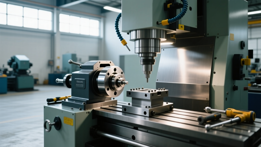
Under ANSI B11.8 standards for drilling and milling machines, the workholding device must remain rigidly affixed to the machine table. The most common compliance failure in job shops is improper T-bolt torque. Over-torquing strips the cast-iron T-slot threads (which typically fail around 180 ft-lbs for 5/8" threads), while under-torquing allows the vise to lift during heavy Z-axis engagement.
| T-Bolt Size | Thread Pitch | Target Torque (Lubricated) | Max Safe Torque (Dry) |
|---|---|---|---|
| 1/2" | 1/2"-13 UNC | 55 ft-lbs | 75 ft-lbs |
| 5/8" | 5/8"-11 UNC | 110 ft-lbs | 140 ft-lbs |
| 3/4" | 3/4"-10 UNC | 190 ft-lbs | 240 ft-lbs |
Jaw retention is equally critical. When machining soft jaws (aluminum or Delrin) for high-mix production, the shear strength of the mounting screws dictates the maximum allowable Y-axis cutting force. Always use Grade 8 or ISO 10.9 socket head cap screws for soft jaw mounting, torqued to 85% of their yield strength, and apply a medium-strength threadlocker (e.g., Loctite 243) to prevent vibrational backing-out.
WARNING: Soft Jaw Failure ModesNever machine soft jaws thinner than 0.375 inches at the gripping edge. Under high hydraulic pressure, thin aluminum jaws will deflect, creating a 'spring-back' effect that reduces the effective grip by up to 40% once the part is seated, leading to micro-movements and catastrophic tool breakage.
Lathe Chucks: Centrifugal Force Loss and RPM Limits
In turning operations, the primary safety hazard is the loss of gripping force due to centrifugal effects. As the spindle accelerates, the mass of the chuck jaws pulls them outward against the scroll or wedge mechanism. According to OSHA machine guarding guidelines and ISO 16089, operators must strictly adhere to the maximum RPM ratings stamped on the chuck body, which are calculated based on the heaviest standard jaws available for that model.
If you switch from standard heavy steel jaws to lightweight aluminum or carbon-fiber top jaws, the safe RPM limit increases, but this must be mathematically validated. Below is a representation of gripping force loss for a standard 10-inch (250mm) 3-jaw power chuck equipped with standard steel master jaws and heavy top jaws.
| Spindle RPM | Centrifugal Force per Jaw | Effective Grip Reduction | Remaining Clamping Force |
|---|---|---|---|
| 1,000 | ~450 lbf | 5% | 95% |
| 2,000 | ~1,800 lbf | 18% | 82% |
| 3,000 | ~4,050 lbf | 38% | 62% |
| 4,000 (Max Rated) | ~7,200 lbf | 65% | 35% |
Note: At 4,000 RPM, the chuck retains only 35% of its static clamping force. If your toolpath requires 40% of static force to prevent part slippage, the part will eject at max RPM. Always calculate dynamic grip, not static grip, for high-speed turning.
Custom Fixtures: Validation and Proximity Sensor Integration
For high-volume production on an icon machine tool, custom hydraulic or pneumatic fixtures are mandatory. Compliance with modern safety standards requires these fixtures to feature 'part-seated' validation. This is achieved through integrated proximity sensors or hydraulic pressure sequence valves.
- Sequence Valves: The hydraulic circuit must be designed so that the clamping cylinders cannot engage until the part-seated cylinder has bottomed out, confirming the part is resting against the hard datum stops.
- Proximity Sensors: Inductive sensors embedded in the fixture body must detect the presence of the raw casting within a 0.020-inch tolerance before the machine's PLC allows the cycle start relay to close.
- Pressure Monitoring: A digital pressure switch must continuously monitor the accumulator line. If pressure drops below 85% of the target clamping pressure (due to a leak or pump failure), the switch must trigger an immediate feed-hold and spindle stop via the machine's M-code interface.
Compliance Checklist for the Shop Floor
Maintaining workholding safety is an ongoing process. Implement this weekly audit checklist to ensure compliance with NIOSH and OSHA machine guarding recommendations:
- Vise Screw Lubrication: Check and reapply moly-based grease to Acme vise screws. Dry screws lose up to 30% of their mechanical advantage due to friction, leading to false torque readings on the handle.
- Chuck Jaw Travel: Inspect lathe chuck jaws to ensure they are gripping within the middle third of their travel range. Gripping at the extreme inner or outer limits drastically reduces the scroll contact area and increases the risk of jaw ejection.
- T-Slot Integrity: Run a finger along the edges of machine T-slots to check for burrs or rolled edges caused by previous over-torquing. Burrs prevent the vise base from sitting flat, creating a pivot point that amplifies cutting forces.
- Collet Runout and Wear: Inspect ER and TG collets for bell-mouthing. A worn collet will grip the tool shank only at the very front edge, reducing pull-out resistance by over 50% and increasing the likelihood of the tool pulling out during high-feed milling.
By treating workholding as a calculated engineering discipline rather than a manual setup task, shops can eliminate part ejection hazards, protect their workforce, and maintain strict adherence to industrial safety compliance.