Machine Tool Safety Interlocks: Gunter Machine and Tool Training
Master machine tool safety interlocks and E-stops with operator training best practices benchmarked from Gunter Machine and Tool protocols.
The Critical Role of Safety Interlocks in Modern Machining
Machine tool safety is not a passive endeavor; it requires active, daily verification by trained operators. According to OSHA's general machine guarding standards (1910.212), any machine part or operation that exposes a worker to injury must be guarded. In the CNC machining sector, this translates directly to door interlocks, spindle brakes, and emergency stop (E-stop) circuits. The Gunter Machine and Tool training framework has emerged as an industry benchmark for teaching operators not just how to use these systems, but how to verify their electrical and mechanical integrity before every shift.
When a 10,000 RPM spindle or a 40-ton press brake operates with compromised safety circuits, the result is catastrophic. This guide breaks down the exact methodologies used in top-tier operator training programs to maintain, test, and respect machine tool safety interlocks and E-stop architectures.
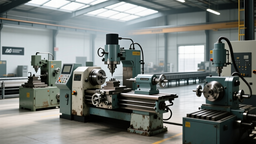
⚠️ WARNING: The "Tape and Zip-Tie" EpidemicShop floor audits consistently reveal that a significant percentage of manual lathe and mill accidents involve bypassed interlocks. Operators frequently use electrical tape over optical sensors or zip-ties on mechanical limit switches to clear chips or load parts without waiting for the spindle to fully decelerate. This practice violates federal safety protocols, invites severe OSHA citations, and fundamentally compromises the machine's safety architecture.
Anatomy of Machine Tool Safety Interlocks
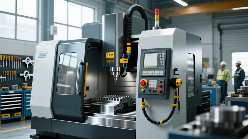
Modern CNC vertical machining centers (VMCs) and multi-axis lathes utilize two primary types of door interlocks. Understanding the difference is the first step in the Gunter Machine and Tool operator curriculum.
Mechanical Tongue Switches vs. RFID Non-Contact Switches
Legacy machines often rely on mechanical tongue interlocks (e.g., Schmersal AZM series). These require a physical metal actuator to slide into a switch housing. While robust, they are highly susceptible to chip packing. If aluminum swarf or cast iron dust jams the actuator slot, the door may register as "closed" when it is actually ajar, or fail to release the solenoid lock when the cycle ends.
Modern training protocols mandate the use of RFID-coded non-contact interlocks, such as the Euchner NZ.VS or Schmersal BNS series. These sensors read a coded transponder in the door handle. They are immune to chip packing, coolant washdowns, and mechanical misalignment up to 5mm. Operators are trained to verify the LED diagnostic indicators on these switches—typically a solid green for safe/closed, and a flashing red for actuator misalignment or fault.
Emergency Stop (E-Stop) Circuit Architecture
An E-stop button is not merely a "pause" button; it is a hardwired safety circuit designed to override all machine logic. Under ISO 13850 standards for emergency stop functions, the system must remove power to hazardous actuators without creating additional risks (such as dropping a suspended axis). Training programs categorize stops into two distinct architectures, as defined by NFPA 79 (Electrical Standard for Industrial Machinery).
| Stop Category | Architecture & Behavior | Application Example | Response Time |
|---|---|---|---|
| Category 0 | Uncontrolled stop. Immediate removal of power to machine actuators via hardwired safety relays. Coast to stop. | Main E-stop button on a Haas VF-2 or Mazak Variaxis. | < 20ms |
| Category 1 | Controlled stop. Power is maintained to drives to brake the spindle and hold axes, then power is removed via safety relays. | Siemens 840D sl controlled spindle stop; automated press brakes. | 200ms - 2.5s |
Operators must understand that a Category 0 stop on a heavy-duty lathe with a massive 4-jaw chuck may result in a prolonged coast-down time due to rotational inertia, even though electrical power is cut in under 20 milliseconds. This physical reality dictates why operators must never open the chuck guard until the spindle has reached absolute zero RPM.
The 5-Step Operator Verification Protocol
The Gunter Machine and Tool methodology requires operators to perform a 45-second verification sequence at the start of every shift. This prevents the "assumed safety" fallacy, where operators trust that a system is working simply because it worked yesterday.
- Visual Tamper Inspection: Walk the machine perimeter. Look for zip-ties, tape, wedged pieces of cardboard, or bypassed limit switches. Check that the E-stop button twist-release mechanism is not physically bound by dried coolant.
- The "Door Open" Spindle Test: With the machine in MDI (Manual Data Input) mode and the spindle rotating at 500 RPM, crack the main door open by 1 inch. The safety interlock must instantly trigger a Category 0 or Category 1 stop. If the spindle continues to cut, the machine must be red-tagged and locked out immediately.
- E-Stop Actuation Under Load: Run a rapid traverse (G00) move on the X and Y axes. Strike the E-stop button mid-move. The axes must halt immediately without throwing a following error that damages the ball screws.
- Reset Logic Verification: Twist and pull the E-stop button to release it. Attempt to reset the machine alarm. The control should require a deliberate secondary action (e.g., pressing a physical "Reset" button on the operator panel) to clear the fault. If the machine auto-restarts upon E-stop release, the safety relay logic is dangerously misconfigured.
- Guard Lock Solenoid Check: For machines equipped with solenoid-locked doors, verify that the door cannot be physically pulled open while the spindle is active. Apply moderate pulling force (approx. 20 lbs) to the handle during a cutting cycle to ensure the locking mechanism is fully engaged.
Upgrading Legacy Machines: Retrofitting Safety Relays
Many shops operate older manual and CNC equipment where the E-stop circuit simply drops power to the main contactor, bypassing modern safety monitoring. Upgrading these machines to dual-channel safety relay architectures is a critical capital investment.
Cost Insight: Retrofitting a standard 3-axis VMC with a dual-channel safety relay system (such as the Pilz PNOZ X3 or Allen-Bradley Guardmaster 440R) typically costs between $4,200 and $8,500. This includes the safety relays ($250–$450 per unit), redundant wiring, E-stop buttons, and 12–16 hours of specialized electrical integration labor.
These dual-channel relays monitor for cross-faults and short circuits. If an operator attempts to jumper a faulty E-stop switch, the safety relay detects the asymmetry between Channel 1 and Channel 2 and permanently locks out the machine until a hard reset is performed by maintenance personnel.
FAQ: Interlocks and E-Stops on the Shop Floor
Q: Can I use the feed hold button instead of the E-stop to pause a program?
A: Yes, for normal program interruptions. Feed Hold pauses axis movement via the CNC control logic but leaves the drives powered and the spindle running. The E-stop is strictly for emergencies where immediate cessation of all hazardous motion and electrical power is required to prevent injury or machine damage.
Q: Why does my machine require a 3-second wait after opening the door?
A: This is a "guard locking with run-down monitoring" feature. The safety relay monitors the spindle encoder. The solenoid lock will not release the door until the encoder confirms the spindle has dropped below a safe threshold (usually 50 RPM), preventing operators from reaching into a spinning chuck.
Q: What happens if a safety interlock switch fails during a cycle?
A: In a properly wired dual-channel system, a switch failure will result in a safe-state fault. The machine will halt, and the control will display a specific safety circuit alarm code. Never attempt to "jumper out" a failed switch to finish a part; this defeats the entire safety architecture and exposes the operator to lethal kinetic energy.