Maintaining Safety Interlocks and E-Stops on Enco Machine Tools
Learn the exact maintenance schedules, testing procedures, and upgrade paths for safety interlocks and E-stops on legacy Enco machine tools.
Enco machine tools, particularly the 110-135 geared head lathe and the 105-1000 knee mill, remain prevalent in job shops and maintenance departments. Following the absorption of the Enco brand by MSC Industrial Direct, OEM electrical support for these legacy machines has largely transitioned to third-party repair and in-house maintenance teams. Because these machines often operate on older single-channel control circuit architectures, the reliability of their safety interlocks and emergency stop (E-stop) circuits degrades predictably over time. Adhering to a rigorous, data-driven maintenance schedule for these safety components is not just a regulatory requirement under OSHA 1910.212 machine guarding standards; it is critical for preventing catastrophic operator injury and minimizing unplanned downtime.
CRITICAL WARNING: Many Enco mills and lathes manufactured between 1995 and 2010 utilize PVC-insulated control wiring routed through high-heat zones near the spindle motor. Over time, this insulation becomes brittle and flakes off, leading to intermittent short circuits that can bypass E-stop logic entirely. Always perform an insulation resistance test (Megger test) at 500V DC on legacy control harnesses before assuming the safety circuit is intact.The Anatomy of Legacy Enco Safety Circuits
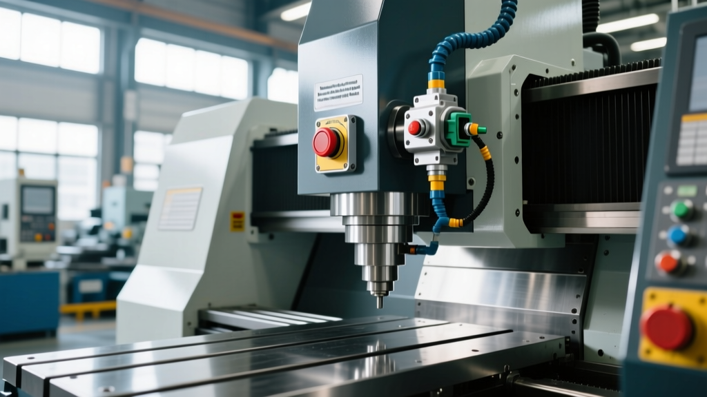
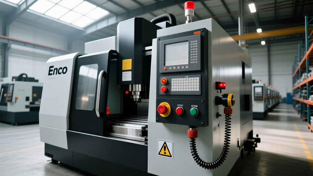
Unlike modern CNC machining centers that utilize solid-state safety PLCs, most manual and early CNC Enco machine tools rely on hardwired, series-connected 110V AC or 24V DC control circuits. In a standard Enco 105-1000 mill, the E-stop mushroom button, the chuck guard limit switch, and the electrical cabinet door interlock are wired in series directly to the coil of the main spindle contactor.
When any of these Normally Closed (NC) contacts opens, the circuit breaks, dropping out the main contactor and cutting 3-phase power to the spindle motor. While simple, this architecture is highly susceptible to single-point failures. If the E-stop contact block becomes carbon-tracked from repeated arcing, it may fail to open the circuit during an emergency, or worse, it may weld itself shut. Maintenance schedules must specifically target the physical degradation of these electromechanical components.
Quarterly Interlock and E-Stop Testing Protocol
Relying on a simple "push the button to see if it stops" visual check is insufficient for compliance and safety. Maintenance technicians must execute the following quantitative testing protocol every 90 days or 500 operating hours, whichever comes first.
- Lockout/Tagout (LOTO) & Visual Inspection: Disconnect main power. Remove the E-stop button housing and inspect the NC contact block (typically a 10A rated block). Look for black carbon scoring on the silver-alloy contact pads. If pitting exceeds 0.5mm in depth, replace the block immediately.
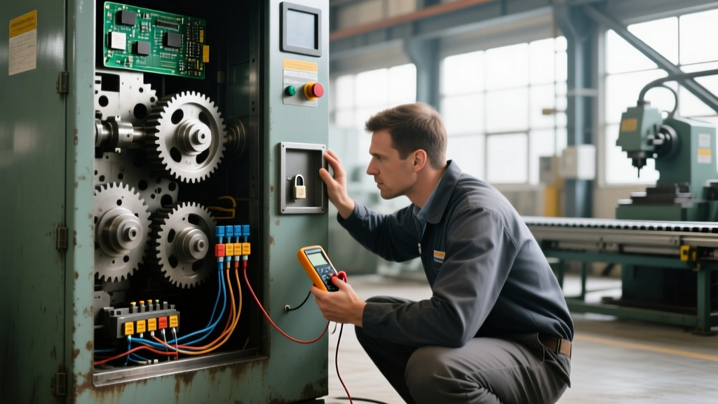
- Contact Resistance Testing: Using a calibrated digital multimeter (e.g., Fluke 87V) set to measure milliohms, measure the resistance across the closed E-stop contacts. A healthy contact block should read less than 0.05 ohms. Readings above 0.5 ohms indicate severe internal degradation that will cause a voltage drop under load, potentially leading to contactor chatter.
- Mechanical Travel Verification: Measure the physical travel distance of the interlock switches on the chuck guard and cabinet doors. Enco lathes often use simple plunger-style limit switches. The plunger must depress at least 3mm past the actuation point to ensure the NC contacts fully open. Adjust the striker plate if travel is less than 2.5mm.
- Contactor Dropout Voltage Test: Restore power and safely monitor the voltage at the main contactor coil while actuating the E-stop. The voltage must drop to 0V within 20 milliseconds. Any residual voltage indicates a parallel leakage path or a failing isolation transformer.
Preventative Maintenance Schedule Matrix
| Interval | Component | Action Required | Tolerance / Spec |
|---|---|---|---|
| Monthly | E-Stop Actuators | Functional drop-out test under no-load | Spindle stops < 2.0 seconds |
| Quarterly | NC Contact Blocks | Contact resistance measurement | < 0.05 ohms |
| Bi-Annually | Guard Limit Switches | Verify plunger travel and striker alignment | Min 3mm over-travel |
| Annually | Main Contactor | Inspect main power poles for arcing/pitting | Replace if pitting > 1.0mm |
Upgrading Legacy Enco E-Stops to ISO 13849 Standards
For shops running Enco machine tools in high-liability environments or those seeking to align with modern ISO 13849-1 safety architectures, retrofitting the legacy single-channel series circuit is a high-ROI project. The standard single-channel E-stop circuit is classified as Category B or 1, meaning a single fault (like a welded contact) leads to a loss of the safety function.
Upgrading to a Category 3 or 4 dual-channel architecture requires replacing the direct-wired E-stop buttons with modern safety relays and dual-channel actuators. This upgrade typically costs between $450 and $800 per machine in parts, but drastically reduces the risk of catastrophic safety failures.
Upgrade Parts List (Per Machine):- Safety Relay: Pilz PNOZ X2.8P or Allen-Bradley 440R-S13R2 (Approx. $280). These monitor dual channels and include a feedback loop to ensure the main contactor actually drops out.
- E-Stop Actuator: IDEC XA1E flush-mount E-stop with dual NC contacts (Approx. $65).
- Contactor Feedback: Add a mechanically linked, mirror-contact auxiliary block (e.g., Schneider LADN02) to the main spindle contactor to wire into the safety relay's feedback loop (Y1/Y2 terminals).
During the retrofit, wire Channel 1 of the E-stop through the primary control circuit, and Channel 2 through the safety relay. The safety relay's output contacts are then wired in series with the main contactor coil. If one channel fails to open, the safety relay detects the asymmetry, locks out the machine, and illuminates a diagnostic fault LED on the relay faceplate, preventing the machine from restarting until the fault is cleared.
Troubleshooting Common Enco Interlock Failures
When Enco machine tools exhibit erratic safety behavior, technicians often misdiagnose the root cause, leading to repeated failures. Use this decision tree to isolate the exact failure mode.
- Symptom: The main spindle contactor chatters loudly or hums when the E-stop is released and the start button is pressed.
Cause: Carbon buildup on the E-stop NC contacts is creating a high-resistance voltage drop. The contactor coil is receiving only 80V instead of the required 110V, causing it to vibrate rather than pull in fully.
Fix: Do not sand or file the contacts. Replace the contact block with a gold-flashed, low-resistance block (e.g., Schneider ZB2BE102) designed for low-current control circuits. - Symptom: The Enco 110-135 lathe spindle continues to coast or restart when the chuck guard is lifted during operation.
Cause: The mechanical striker on the polycarbonate chuck guard has warped due to coolant exposure and heat, failing to fully depress the microswitch plunger. Alternatively, coolant has infiltrated the microswitch, shorting the NC contacts internally.
Fix: Replace the standard microswitch with an IP67-rated, sealed solenoid interlock switch (e.g., Schmersal AZM161, approx. $180). This prevents coolant ingress and requires a deliberate electrical release to open the guard while the spindle is rotating. - Symptom: Pressing the E-stop stops the spindle, but the axis power feeds on the Enco mill do not disengage.
Cause: The original factory wiring on many Enco mills routes the E-stop only through the spindle contactor, leaving the separate 24V DC feed motor transformer energized. This is a severe design flaw in older models.
Fix: Install a secondary master control relay (MCR) triggered by the E-stop circuit. Wire the primary side of the feed motor transformer and the coolant pump contactor through the NC contacts of the MCR, ensuring a complete machine-wide power cutoff.
"Safety circuits on legacy manual machines are only as reliable as their last physical inspection. A continuity test with a multimeter will not reveal a contact block that is mechanically binding and arcing internally under load. Technicians must measure voltage drop across closed safety contacts while the machine is actively running to uncover hidden resistance faults."
By transitioning from reactive part replacement to a predictive maintenance schedule focused on contact resistance, mechanical travel tolerances, and dual-channel upgrades, maintenance teams can ensure that legacy Enco machine tools remain both highly productive and strictly compliant with modern safeguarding requirements.