Car Key Cutting Machine: Chip Conveyor Systems
Explore chip conveyor systems for the car key cutting machine tool. Micro-chip conveyors and brass dust extraction specs inside.
The Unique Swarf Profile of Automotive Key Manufacturing
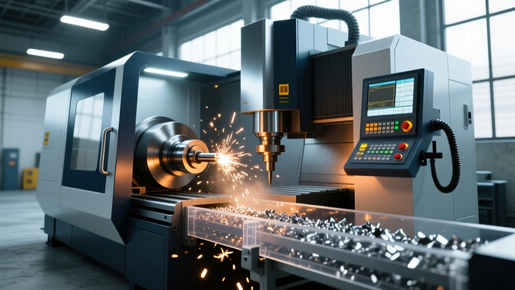
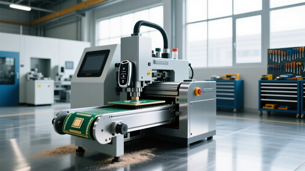
High-volume automotive key manufacturing relies on specialized CNC broaching and milling equipment. When operating a high-speed car key cutting machine tool to produce intricate transponder grooves, laser-track dimples, and high-security sidewinder profiles, the resulting swarf presents unique metallurgical and morphological challenges. Unlike standard steel milling, which produces predictable C-shaped chips, key blank machining generates a highly heterogeneous mix of particulate matter. Managing this waste requires highly specialized chip conveyor systems engineered specifically for non-ferrous, micro-particulate, and stringy swarf profiles.
Metallurgy of Key Blanks and Swarf Morphology
To design an effective swarf management system, one must first understand the workpiece materials. Modern automotive key blanks are predominantly milled from three distinct alloys, each producing a drastically different chip morphology:
- CZ121 (CW614N) Free-Machining Brass: Used for standard transponder key blades. The addition of lead to this alloy results in short, brittle, fragmented chips and a high volume of fine brass dust (10-50 microns). According to Sandvik Coromant's machining fundamentals, free-machining brass generates discontinuous chips that easily jam standard hinge-belt conveyors by slipping between the belt hinges.
- Nickel-Silver (Cupronickel): Utilized for high-security sidewinder and laser-cut keys due to its wear resistance. This material work-hardens rapidly, producing long, stringy, and highly abrasive continuous chips that can wrap around conveyor drive shafts and auger flighting.
- 6061-T6 Aluminum: Increasingly used for the outer shells of smart-key fobs. Aluminum milling at high spindle speeds (often exceeding 15,000 RPM on key cutting tools) generates gummy, built-up edge (BUE) prone chips that adhere to conveyor surfaces if not properly lubricated.
Milling these materials requires spindle speeds ranging from 8,000 RPM for heavy brass broaching up to 24,000 RPM for fine aluminum smart-key shell profiling, drastically altering the kinetic energy of the ejected chips and the required capture velocity of the extraction system.
Critical Safety Warning: Fine brass and aluminum dust generated during high-speed key milling are classified as combustible. The OSHA combustible dust guidelines mandate strict capture velocities and grounded extraction systems to prevent static-induced deflagration in the swarf collection bin.Technical Specifications of Micro-Chip Conveyors
Standard heavy-duty steel hinge-belt conveyors are entirely unsuited for the car key cutting machine tool environment. Instead, modern key manufacturing facilities utilize a dual-stage extraction approach combining auger and pneumatic conveyors.
Auger Conveyor Specifications for Stringy Swarf
To handle the nickel-silver stringy chips, industrial key cutting centers employ enclosed tubular auger conveyors. The technical specifications for these units are highly precise:
- Motor Torque: 0.75 kW servo motors paired with a 15:1 planetary gearbox. This provides the low-speed, high-torque rotation required to shear through jammed nickel-silver tangles without stripping the auger flighting.
- Pitch and Flighting: A 45mm pitch with a specialized polyurethane outer lip. The polyurethane lip creates a near-zero clearance against the stainless steel tube, preventing fine brass dust from accumulating in the trough and causing abrasive wear.
- Variable Frequency Drive (VFD): Programmed with an auto-reverse jam-clearing cycle. If current draw spikes by 15% (indicating a chip tangle), the VFD reverses the auger for 1.5 seconds before resuming forward extraction.
- Access Panels: The auger trough features a hinged, quick-release access panel secured by toggle clamps, allowing operators to clear catastrophic nickel-silver jams in under 60 seconds without requiring specialized tools.
Pneumatic Extraction for Micro-Dust
The fine brass and aluminum particulate must be evacuated via high-velocity pneumatic suction. The transport velocity within the extraction ducting must maintain a minimum of 22 m/s (approximately 4,300 FPM). If velocity drops below 18 m/s, the heavier brass particulates fall out of suspension, accumulating in horizontal duct runs and eventually causing a total system blockage.
Comparison Matrix: Conveyor Types for Key Cutting Swarf
| Conveyor Type | Target Swarf Material | Optimal Velocity / RPM | Primary Failure Mode | Cost Estimate (2026) |
|---|---|---|---|---|
| Hinge-Steel Belt | Cast Iron, Steel | 15-25 m/min | Fine brass dust infiltration seizing hinges | $3,500 - $5,000 |
| Enclosed Tubular Auger | Nickel-Silver, Stringy Chips | 12-18 RPM | Shaft wrapping and flighting shear | $4,200 - $6,800 |
| Pneumatic Vacuum | Brass Dust, Aluminum Fines | 22+ m/s (Airflow) | Filter blinding and static buildup | $8,500 - $12,000 |
| Vibratory Trough | Wet, Gummy Aluminum | 800-1200 VPM | Coolant emulsion drying and cementing chips | $2,800 - $4,500 |
How Pneumatic Swarf Extraction Works in Key Cutting
The integration of pneumatic extraction directly at the cutting zone of a car key cutting machine tool requires precise fluid dynamics engineering. Here is the step-by-step operational sequence:
- Capture Zone Generation: A localized shroud surrounds the milling spindle, utilizing a 150mm diameter extraction hood. The hood is positioned exactly 75mm from the cutting edge to maximize capture velocity without disrupting the localized mist-coolant delivery.
- Airflow Acceleration: A regenerative blower (typically 5.5 kW) generates a negative pressure of -25 kPa at the source. The air accelerates through a venturi nozzle, picking up both the dry brass dust and the aerosolized metalworking fluid.
- Cyclonic Separation: The air-swarf mixture enters a primary cyclonic separator. The centrifugal force throws the heavier brass and nickel-silver chips against the outer wall, where they drop into the collection drum. This stage removes 85% of the particulate mass.
- HEPA Filtration and Coolant Coalescing: The remaining air, carrying sub-10 micron dust and coolant mist, passes through a MERV 15 coalescing filter followed by a HEPA stage. This ensures the exhaust air meets indoor air quality standards, a critical requirement outlined by NIOSH metalworking fluid guidelines to prevent operator respiratory issues.
Engineering Insight: Never route the pneumatic exhaust of a brass key cutting machine directly outside without thermal compensation. Exhausting 3,000 CFM of climate-controlled shop air in winter will drastically alter the ambient temperature of the machining floor, causing thermal expansion errors in the CNC machine's ball screws and ruining the tight tolerances required for transponder key grooves.
Maintenance Protocols and Edge Cases
Even the most rigorously specified chip conveyor system will fail if maintenance protocols ignore the specific edge cases of key manufacturing swarf.
Static Cling and Filter Blinding
Brass dust is highly susceptible to triboelectric charging (static buildup) as it travels through PVC ducting. This static charge causes the fine dust to cling to the interior walls of the ducting and rapidly blind the surface of the HEPA filters. To mitigate this, all extraction ducting must be manufactured from statically dissipative polyurethane (surface resistivity of 10^6 to 10^8 ohms/sq) and physically bonded to the facility's earth ground. Furthermore, filter pulse-jet cleaning systems must be set to fire every 45 seconds, rather than the standard 5-minute interval used in steel machining, to prevent the brass dust from embedding into the filter media.
Coolant Emulsion Cementing
When machining aluminum smart-key shells, the swarf is often coated in a semi-synthetic metalworking fluid. If this swarf sits stationary in a vibratory trough or collection bin over a weekend, the fluid's water content evaporates, leaving behind a resinous binder that essentially cements the aluminum chips into a solid brick. Operators must implement a mandatory dry-run protocol at the end of every Friday shift: running the conveyors empty for 15 minutes while spraying a light mist of pure water to flush the emulsion residue from the trough surfaces. Failure to execute this flush results in operators spending 2-3 hours manually chipping out hardened aluminum swarf with brass scrapers, risking severe damage to the conveyor's polyurethane lining.
By aligning the chip conveyor specifications with the exact metallurgical realities of automotive key blanks, manufacturing facilities can eliminate unplanned downtime, maintain strict dimensional tolerances, and ensure a safe, combustible-dust-free environment.