Maintaining Advance Machine Tools: Calibration & Accuracy Standards
Master advance machine tools calibration with our maintenance schedule guide. Learn ISO accuracy standards, laser interferometry, and service intervals.
The Financial Impact of Volumetric Error
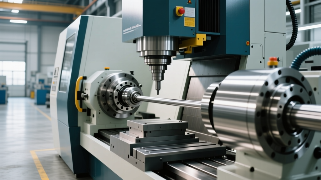
Operating advance machine tools—such as 5-axis trunnion mills and multi-tasking turn-mill centers—without a rigorous calibration schedule is a silent margin killer. In high-tolerance aerospace and medical machining, a volumetric error of just 15 microns can scrap a $4,000 titanium turbine blade. While modern CNC controllers feature sophisticated thermal compensation algorithms, these software patches cannot correct physical geometric degradation. Ballscrew pitch wear, guideway stick-slip, and spindle thermal drift compound across the working envelope, transforming a $250,000 investment into an unpredictable liability.
⚠️ The Abbe Error Multiplier: A common oversight in advance machine tools maintenance is ignoring the Abbe offset. If your Z-axis spindle has a 150mm Abbe offset from the linear scale, a mere 10 arc-second yaw error in the column will induce a 7.2 µm linear displacement error at the tool tip. Physical calibration is the only way to map and compensate for this geometric reality.Decoding ISO 230 and ASME B5.54 Standards
To establish a baseline for maintenance, shop floors must align their service schedules with international metrology standards. The ISO 230 series provides the definitive test codes for machine tool accuracy, dictating everything from linear axis positioning to rotary axis centerlines.
| Standard | Focus Area | Calibration Tool Required | Recommended Interval |
|---|---|---|---|
| ISO 230-2 | Linear Axis Positioning (Accuracy & Repeatability) | Laser Interferometer | Annually |
| ISO 230-4 | Circular Interpolation (Contouring Performance) | Telescoping Ballbar | Quarterly |
| ISO 230-6 | Volumetric Accuracy (Diagonal Displacement) | Laser Tracker / Step Gauge | Bi-Annually |
| ISO 230-7 | Axes of Rotation (Spindle & Rotary Tables) | Capacitance Probe / Autocollimator | Annually |
The 3-Tier Maintenance and Calibration Schedule
Effective maintenance of advance machine tools requires a stratified approach, moving from daily operator habits to annual metrology lab interventions.
Tier 1: Daily Operator Warm-Up & Thermal Stabilization
Thermal growth accounts for up to 70% of all geometric errors in CNC machining. A cold start on a 5-axis machine will yield drastically different tool center point (TCP) coordinates than a machine running at thermal equilibrium.
- Spindle Warm-Up Macro: Execute a 15-minute warm-up cycle. Run the spindle at 30% max RPM for 5 minutes, 60% for 5 minutes, and 80% for 5 minutes. This stabilizes the spindle bearing preload and housing expansion.
- Axis Sweeps: Command all linear axes to travel 80% of their stroke at rapid traverse (G00) for 3 minutes to distribute way lubricant and stabilize the ballscrew temperature.
- Coolant Temperature: Verify the chiller unit is maintaining the coolant within ±0.5°C of ambient room temperature (typically 20°C / 68°F). Check the glycol-to-water ratio; a 30/70 mix is optimal for preventing biological growth while maintaining thermal transfer efficiency.
Tier 2: Quarterly Ballbar Diagnostics
Every 500 operating hours, maintenance technicians should perform a telescoping ballbar test (e.g., using the Renishaw QC20-W). This 15-minute test evaluates circular interpolation, revealing critical servo and mechanical faults.
💡 Pro Tip for Ballbar Testing: Always run the ballbar test at two different feed rates (e.g., 1,000 mm/min and 3,000 mm/min on a 150mm radius). If the servo lag spikes at the higher feed rate but remains stable at the lower rate, you are looking at a servo tuning or gain mismatch issue, not a mechanical backlash problem.Tier 3: Annual Laser Interferometry & Pitch Error Compensation
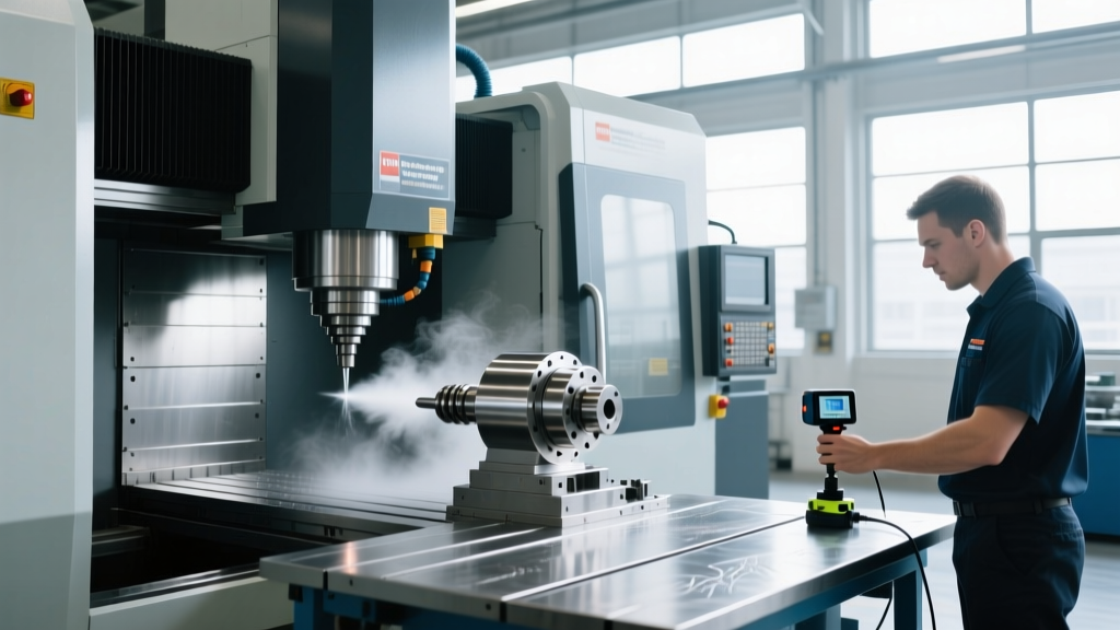
Once a year, advance machine tools require linear positioning calibration via laser interferometry. Systems like the Renishaw XL-80 or API laser trackers measure the actual position of the axis against the commanded position, identifying pitch errors caused by ballscrew wear or thermal expansion of the screw itself.
During this service, technicians must also apply environmental compensation. Air temperature, barometric pressure, and humidity alter the wavelength of the laser beam. Failing to input these variables into the calibration software will introduce errors of up to 1.5 µm per meter of travel.
Diagnostic Decision Matrix: Axis Drift & Geometric Faults
When advance machine tools fail to hold tolerance, use this diagnostic framework to isolate the root cause before calling a service technician.
- Symptom: Ovality in precision bored holes, specifically aligned with the X or Y axis reversal points.
Cause: Ballscrew backlash or stick-slip friction on the guideways.
Action: Check way lube pressure (must be 1.5 to 2.5 bar). Inspect metering valves for a full 3mm stroke. If lube is optimal, adjust the CNC controller's backlash compensation parameter by 0.005mm increments. - Symptom: Z-axis depth shifts of 10-20 µm during the first hour of a production run, stabilizing afterward.
Cause: Spindle housing thermal growth outpacing the machine's native thermal compensation model.
Action: Clean the spindle chiller condenser filters. Verify the thermal sensors on the spindle casting are free of coolant residue and making solid contact. Update the machine's thermal displacement compensation table. - Symptom: 5-axis RTCP (Rotary Tool Center Point) errors exceeding 25 µm during simultaneous contouring.
Cause: Trunnion table rotary axis centerline drift or worn preloaded bearings in the tilt axis.
Action: Perform an ISO 230-7 rotary axis calibration using a capacitance probe and precision test mandrel. Re-shim the trunnion bearings or adjust the worm gear mesh preload.
Procurement: In-House vs. Third-Party Calibration Services
Deciding whether to bring calibration in-house or outsource it depends on your fleet size and tolerance requirements. Purchasing a full laser interferometer system requires a capital expenditure of $55,000 to $85,000, plus the cost of training a certified metrologist. For job shops with fewer than five advance machine tools, outsourcing to an ISO 17025-accredited calibration lab is the most economical route, typically costing between $3,500 and $6,000 per machine for a full geometric and volumetric mapping.
However, for high-volume aerospace tier-1 suppliers running 20+ multi-axis cells, investing in in-house laser tracker technology pays for itself within 14 months by eliminating machine downtime associated with waiting for third-party vendors. Modern laser trackers allow maintenance teams to perform volumetric error mapping in under four hours, feeding compensation data directly into the CNC controller's kinematic chain parameters.
"Calibration is not a repair activity; it is a predictive baseline. If you only calibrate your advance machine tools when they start scrapping parts, you have already lost thousands of dollars in undetected tool wear and scrapped material. Schedule the laser, trust the data, and update the kinematic tables."
— Lead Metrology Engineer, Tier 1 Aerospace Manufacturer
Final Verification Protocol
After any calibration parameters are loaded into the CNC controller, always cut a standardized test piece (such as the NAS 979 circle-diamond-square test). Measure the test piece on a calibrated CMM to verify that the machine's physical cutting performance matches the laser interferometry data. This closed-loop verification ensures your advance machine tools remain capable of holding the tightest geometric dimensioning and tolerancing (GD&T) callouts in modern manufacturing.