Precision Milling Machine Tool Holder Applications: 2026 Case Studies
Explore 2026 case studies on milling machine tool holder applications in aerospace titanium roughing and medical micro-machining, featuring runout data.
The true cost of a spindle crash or a scrapped $40,000 aerospace blisk is never just the price of the broken carbide end mill. In 2026, with 5-axis machining centers running at $400 to $850 per hour, the interface between the spindle and the cutting tool is the most critical, yet frequently misunderstood, variable in subtractive manufacturing. Selecting the correct milling machine tool holder is no longer a matter of defaulting to standard ER collets; it requires a rigorous analysis of damping characteristics, radial runout, and clamping force relative to the specific workpiece material.
This report examines two high-stakes industry applications—aerospace titanium roughing and medical micro-machining—detailing the exact toolholding solutions that engineering teams deployed to eliminate chatter, prevent tool pull-out, and achieve sub-micron surface finishes.
Case Study 1: Aerospace Titanium Roughing (Ti-6Al-4V)
The Production Challenge
A Tier-1 aerospace supplier in Ohio was tasked with heavy roughing of Ti-6Al-4V engine structural components using a Makino a99x 5-axis horizontal machining center. The operation utilized a 1.25-inch diameter, 5-flute variable helix carbide end mill. At aggressive material removal rates (MRR) exceeding 12 cubic inches per minute, the cutting forces generated immense radial loads.
The facility initially used standard CAT50 ER40 collet chucks. Within three weeks, the engineering team documented two critical failures:
- Tool Pull-Out: The axial clamping force of the ER40 nut (approximately 1,800 lbs) was insufficient to counteract the axial cutting forces during deep-cavity helical interpolation, causing the tool to creep out of the collet and scrap a $65,000 forging.
- Fretting Corrosion: Micro-movements between the collet and the tool shank generated fretting corrosion, degrading the tool shank and necessitating premature replacement of $180 carbide cutters.
The Engineering Solution: Mechanical Milling Chucks
To resolve the pull-out issue without sacrificing the damping required to prevent chatter, the team transitioned to a mechanical milling machine tool holder system—specifically, the Rego-Fix powRgrip system paired with HSK-A100 interfaces. Unlike hydraulic chucks which can struggle with heavy side-load roughing, mechanical chucks utilize a high-tension outer sleeve pressed over a specialized collet, generating clamping forces exceeding 3,500 lbs.
Production Data Snapshot (Post-Implementation)- Interface: HSK-A100 (providing dual-contact face and taper seating for Z-axis stability at high RPM).
- Clamping Force: Increased from 1,800 lbs (ER40) to 3,850 lbs (Mechanical Chuck).
- Runout: Maintained at < 3 µm at 3× diameter, extending tool life by 34%.
- Cost per Holder: $585 (2026 pricing), offset by a 41% reduction in scrapped parts within the first quarter.
By incorporating tools with Weldon flats or proprietary anti-pull-out grooves (such as the Haimer Safe-Lock system), the mechanical chuck physically locks the tool in the Z-axis. The result was a complete elimination of tool pull-out during heavy titanium roughing, allowing the shop to increase feed rates by 18% without triggering spindle load alarms.
Case Study 2: Medical Micro-Machining (Orthopedic Implants)
The Production Challenge
Manufacturing cobalt-chromium (CoCr) and titanium knee joint implants requires 5-axis simultaneous finishing passes with micro-end mills ranging from 0.5mm to 2.0mm in diameter. A medical device manufacturer in Minnesota was struggling with surface finish inconsistencies on the articular surfaces of femoral components. The required surface roughness was Ra 0.1 µm, but their existing process was yielding Ra 0.35 µm, requiring expensive and time-consuming manual electropolishing to meet FDA submission specs.
The root cause was traced to the toolholding system. The shop was using premium ER16 collet chucks. While ER16 collets are versatile, their inherent design allows for a total indicated runout (TIR) of 8 to 12 µm. When spinning a 1.0mm end mill at 45,000 RPM, a 10 µm runout means the tool is effectively cutting 20% wider than its diameter, causing severe chatter, accelerated flank wear, and visible tool marks on the CoCr workpiece.
The Engineering Solution: Thermal Shrink-Fit Holders
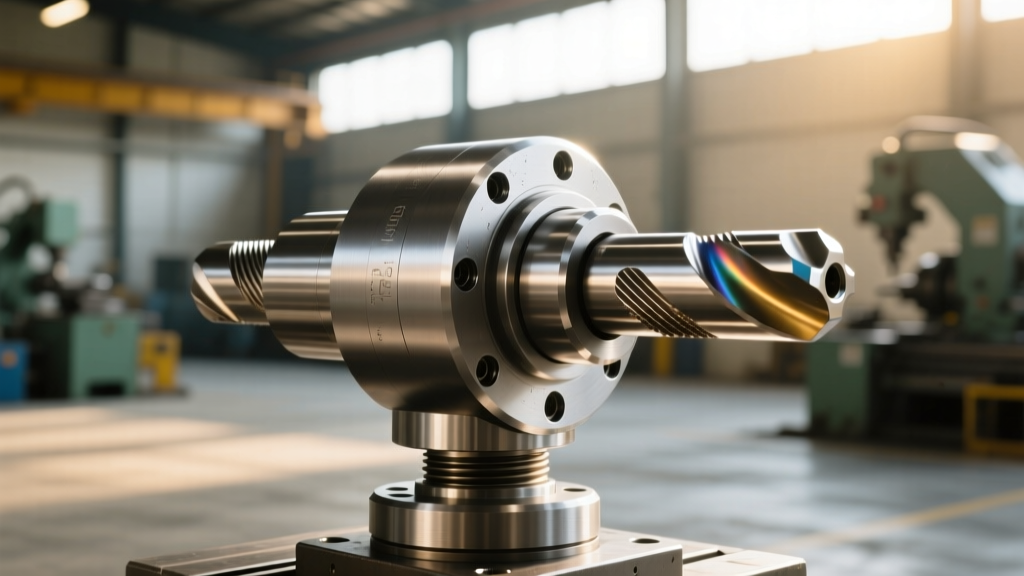
The engineering team replaced the ER16 collets with thermal shrink-fit tool holders, utilizing an induction heating unit to expand the holder's bore, insert the h6-tolerance carbide shank, and allow it to cool for a uniform, 360-degree clamping grip. As detailed in industry guidelines on advanced workholding and toolholding strategies, shrink-fit technology provides the lowest possible mass and the highest rigidity for high-speed micro-machining.
| Holder Type | TIR at 3×D | G4000 Balance (RPM) | Approx. Unit Cost | Best Application |
|---|---|---|---|---|
| ER16 Collet Chuck | 8 - 15 µm | 25,000 | $220 | General purpose roughing |
| Hydraulic Chuck | 3 - 5 µm | 42,000 | $450 | Reaming, light finishing |
| Thermal Shrink-Fit | < 3 µm | 60,000+ | $165 | High-speed micro-finishing |
The implementation of shrink-fit holders reduced runout to under 2 µm. Because the holder is perfectly symmetrical with no flats, nuts, or set-screws, it can be balanced to G0.4 standards at 60,000 RPM natively. The medical facility achieved the target Ra 0.1 µm surface finish directly off the machine, entirely eliminating the secondary electropolishing step and saving 42 hours per batch.
Failure Mode Analysis: Why Holders Fail in Production
Understanding how and why a milling machine tool holder fails is critical for predictive maintenance in 2026's automated lights-out manufacturing environments. The three most common failure modes include:
- Centrifugal Expansion: At spindle speeds exceeding 20,000 RPM, the centrifugal force causes the spindle taper to expand microscopically. If the tool holder is not designed for high-speed expansion (or lacks a retention knob with the correct pull-stud geometry), the holder will pull back into the spindle, altering the Z-axis datum and causing a crash. Always verify the pull-stud thread and angle (e.g., 45-degree vs. 90-degree) against the specific machine builder's 2026 specification sheet.
- Thermal Growth Discrepancies: In heavy roughing, heat transfers from the cutting zone up the carbide shank into the holder. If the thermal expansion coefficient of the tool shank differs significantly from the holder material, clamping pressure can degrade mid-cycle. Hydraulic holders mitigate this via internal fluid chambers, but mechanical chucks maintain grip through elastic deformation limits.
- Taper Fretting: Repeated insertion and removal of CAT40 or BT40 holders without strict cleaning protocols leads to microscopic debris embedding in the spindle taper. This causes uneven seating, resulting in severe radial runout at the tool tip. Implementing automated taper-cleaning systems on robotic tool changers is now considered mandatory for aerospace job shops.
2026 Procurement Framework for Tooling Engineers
When capitalizing a new machining cell or upgrading an existing process, tooling engineers should apply the following decision matrix to specify the correct milling machine tool holder:
- If the operation is heavy roughing in hard metals (Titanium, Inconel, Tool Steels): Specify mechanical milling chucks or heavy-duty hydraulic chucks with anti-pull-out grooves. Prioritize clamping force over extreme high-speed balancing.
- If the operation is high-speed finishing (Aluminum aerospace structures, Medical CoCr): Specify thermal shrink-fit holders. The low mass and superior balance will protect the spindle bearings from vibration-induced degradation while ensuring superior surface finishes.
- If the operation requires frequent tool changes and flexibility (Job shops, prototyping): High-precision ER collet systems remain the most economical choice, provided the shop invests in premium sealed collets and enforces strict 500-cycle replacement schedules to prevent clamping fatigue.
"The spindle is the heart of the machine tool, and the tool holder is the cardiovascular system delivering the work. Compromising on a $200 tool holder to protect a $60,000 spindle is a mathematical failure that modern manufacturing analytics simply will not tolerate."
— Dr. Aris Thorne, Director of Machining Dynamics, Advanced Manufacturing Research Institute.
Ultimately, the modern milling machine tool holder is a precision instrument, not a commodity accessory. By aligning the holder's physical mechanics—whether mechanical, hydraulic, or thermal—with the specific cutting forces and speed requirements of the application, manufacturers can unlock hidden capacity, extend spindle life, and guarantee part conformity in the most demanding sectors of the global supply chain.