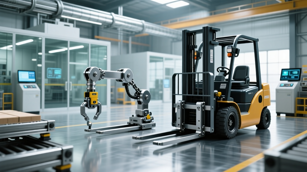
AMR vs AGV Troubleshooting for Warehouse Material Handling Equipment
Diagnose navigation, sensor, and drive failures in AMRs and AGVs. Compare SLAM drift fixes for AMRs with magnetic tape repairs for traditional AGVs.
The diagnostic approach for autonomous mobile robots (AMRs) and automated guided vehicles (AGVs) diverges fundamentally at the navigation layer. While both move payloads across facility floors, AGVs rely on deterministic physical guides (magnetic tape, inductive wire, or QR grids), whereas AMRs utilize probabilistic sensor fusion (LiDAR, wheel odometry, and IMUs) to navigate dynamically. When a unit faults, technicians must apply entirely different troubleshooting trees based on the underlying architecture. Misdiagnosing an AMR localization error as a drive fault, or treating an AGV tape-degradation issue as a sensor failure, results in unnecessary downtime and expensive part replacements.
Diagnostic Matrix: Symptom to Root Cause Mapping
Before opening control cabinets or connecting diagnostic laptops, map the physical symptom to the probable architectural failure. Use this matrix to isolate the subsystem requiring attention.
| Observed Symptom | AGV Root Cause (Deterministic) | AMR Root Cause (Probabilistic) | Primary Diagnostic Tool |
|---|---|---|---|
| Unit stops abruptly mid-route | Magnetic tape peeling or inductive wire signal drop | LiDAR occlusion or SLAM localization loss | Tape gaussmeter / AMR mapping GUI |
| Drifting off the centerline | Guide sensor misalignment or dirt accumulation | Polyurethane drive wheel wear altering odometry | Feeler gauge / Wheel caliper |
| Failure to initiate movement | Safety PLC triggered by physical bumper switch | Compute unit thermal throttling or BMS CAN fault | Multimeter / Thermal camera |
| Erratic spinning in place | Differential drive encoder cable pinch | Multi-path LiDAR error from reflective shrink wrap | Oscilloscope / LiDAR point-cloud viewer |
AGV Diagnostics: Tape, Wire, and Sensor Calibration
Traditional AGVs, such as the Toyota ProTrax or Seegrid GP8 (in wire-guided mode), require physical infrastructure maintenance. The most common AGV fault is a loss of the guidance signal, triggering an immediate safety stop.
Magnetic Tape Degradation and Repair
AGVs using magnetic tape rely on Hall-effect sensors positioned 15mm to 25mm above the floor. Over time, forklift traffic and floor scrubbers degrade the magnetic flux density of the tape. If the flux drops below 30 Gauss, the AGV will fault.
- Testing: Use a handheld gaussmeter (such as the AlphaLab GM-2) to measure the tape's magnetic field. Readings below 35 Gauss indicate impending failure.
- Cleaning: Before replacing tape, clean the surface with 90% isopropyl alcohol. Avoid ammonia-based cleaners, which can degrade the adhesive and magnetic strontium ferrite particles.
- Repair: Replace damaged sections with 3M Scotchmark 700-series magnetic tape. Ensure a 2-inch overlap with the existing tape, and feather the edges with a rubber roller to prevent forklift tires from catching the seam.
Inductive Wire Fault Isolation
For AGVs following buried or surface-mounted inductive wires carrying a 20kHz to 50kHz AC signal, a wire break will cause a total system halt. Do not blindly dig up the floor. Connect a Time Domain Reflectometer (TDR) to the wire loop at the generator. The TDR will send a pulse down the wire and measure the reflection time, pinpointing the exact distance to the break (usually within a 1-foot margin of error).
Warning: AGV Guide Sensor AlignmentWhen replacing a damaged guide sensor (e.g., a Pepperl+Fuchs FGS series), technicians often bolt the new sensor flush with the chassis. This is incorrect. The sensor must be precisely centered over the drive axle and angled exactly perpendicular to the floor. A 2-degree tilt can cause the AGV to weave, accelerating tire wear and causing premature tape destruction.
AMR Diagnostics: SLAM Drift, LiDAR Occlusion, and Odometry
AMRs like the Mobile Industrial Robots (MiR) MiR250 or Fetch Robotics Freight1500 do not follow physical lines. They use Simultaneous Localization and Mapping (SLAM). Troubleshooting AMRs requires analyzing software states, sensor data quality, and mechanical wear that affects dead-reckoning.
LiDAR Occlusion and Multi-Path Errors
AMRs typically use 2D safety LiDARs (like the SICK microScan3) for obstacle avoidance and 3D LiDAR or RGB-D cameras for localization. If an AMR halts in an open aisle, check for 'ghost obstacles'.
- The Shrink-Wrap Problem: Highly reflective pallet shrink-wrap can cause the 905nm laser to scatter, creating multi-path reflections. The SLAM algorithm interprets this scattered light as a solid object. Repositioning the pallet or applying a matte-finish top sheet resolves this without altering the robot's firmware.
- Optical Cover Micro-Scratches: Never clean a SICK or Velodyne LiDAR cover with standard shop rags or paper towels. Micro-scratches scatter the laser beam, degrading the point cloud density. Use only lint-free microfiber and optical-grade cleaning solution.
Wheel Odometry and SLAM Drift
AMRs use wheel encoders to estimate distance traveled between LiDAR scans (dead-reckoning). If the polyurethane drive wheels wear down, the physical diameter decreases. The encoder still counts the same number of revolutions, but the robot travels a shorter physical distance. This discrepancy causes 'SLAM drift', where the robot's internal map position diverges from its actual physical position, eventually causing a localization fault.
Actionable Fix: Measure the drive wheel diameter monthly with a digital caliper. If the diameter has reduced by more than 5% from the factory specification (e.g., dropping from 200mm to 190mm), replace the wheels and update the wheel-diameter parameter in the AMR's ROS (Robot Operating System) configuration file.
Step-by-Step AMR Localization Recovery
When an AMR becomes 'lost' (localization confidence drops below 20%), follow this recovery protocol before rebooting the system:
- Halt Autonomous Mode: Switch the unit to manual joystick control via the fleet management GUI.
- Clear Dynamic Obstacles: Ensure no temporary pallets or personnel are within 3 meters of the robot, as these block the LiDAR's view of static map features.
- Execute a 'Spin-in-Place': Rotate the AMR 360 degrees slowly. This allows the 2D LiDAR to capture a full sweep of permanent structural features (pillars, walls, racking uprights) to re-match against the static map.
- Relocate to a Landmark: If the spin fails, drive the AMR manually to a predefined 'recovery zone' (usually an intersection with high-contrast structural features or artificial QR code landmarks) and trigger the 'Re-localize' command in the software.
Power Systems: BMS and CAN Bus Faults
Both AGVs and AMRs utilize Lithium Iron Phosphate (LiFePO4) or Nickel Manganese Cobalt (NMC) battery packs managed by a Battery Management System (BMS). The BMS communicates with the main controller via a CAN bus. A common, misdiagnosed fault is the robot refusing to drive despite showing an 80% state-of-charge (SOC).
This is usually caused by cell imbalance. If one cell group drops below the low-voltage threshold (e.g., 2.5V for LiFePO4) under the heavy load of acceleration, the BMS will open the main contactor to prevent thermal runaway, instantly killing power to the drive motors. Connect a CAN bus analyzer (like a PCAN-USB) to read the raw BMS hex data. Look for the maximum delta-voltage between cell groups. If the delta exceeds 150mV, the battery requires an extended top-balance charge cycle on a bench charger, or the pack must be replaced. According to OSHA guidelines on powered industrial trucks, only trained personnel should bypass or modify battery safety interlocks, as LiFePO4 thermal events can occur if cell balancing is ignored.
Repair Cost and Downtime Comparison
Understanding the financial impact of these failures helps warehouse managers decide whether to maintain legacy AGV infrastructure or transition to AMR fleets. The data below reflects average 2026 enterprise repair costs.
| Component / Failure Type | AGV Repair Cost & Time | AMR Repair Cost & Time |
|---|---|---|
| Navigation Infrastructure | $0.50 - $1.20 / linear ft (Tape replacement) | $0 (Software map update) |
| Primary Sensor Replacement | $400 - $800 (Guide sensor) / 1 hour | $3,500 - $8,000 (3D LiDAR) / 3 hours |
| Drive Wheel Replacement | $150 per wheel / 2 hours | $250 per wheel + software calibration / 2.5 hours |
| Average Annual Maint. per Unit | $2,500 - $4,000 (Heavy infrastructure focus) | $1,200 - $2,000 (Software & sensor focus) |
AGV troubleshooting is inherently mechanical and infrastructure-dependent; your maintenance team will spend more time on the floor with tape measures and multimeters. AMR troubleshooting is heavily software and data-driven; your team will spend more time analyzing point-cloud data, ROS logs, and CAN bus traffic. As noted in recent Material Handling Institute (MHI) reports, facilities transitioning from AGVs to AMRs must retrain their maintenance staff from electrical/mechanical technicians to mechatronics and network diagnostics specialists to minimize mean-time-to-repair (MTTR).
For further safety protocols regarding human-robot interaction zones and emergency stop circuitry, maintenance supervisors should consult the NIOSH Robotics and Occupational Safety guidelines to ensure all physical repairs comply with current ANSI/RIA R15.08 safety standards for industrial mobile robots.
Related reading

Cleanroom Storeroom Semi-Automated Material Handling Equipment Inventory Solutions
Budgeting Washdown Fleets: Reviews of Auction Platforms for Forklift and Material Handling Equipment in Food & Pharma