Inside the X Machine 5 Axis CNC: Kinematics and Technical Specs
Explore the technical specifications, kinematics, and RTCP calibration of the X machine 5 axis CNC for high-precision complex part production.
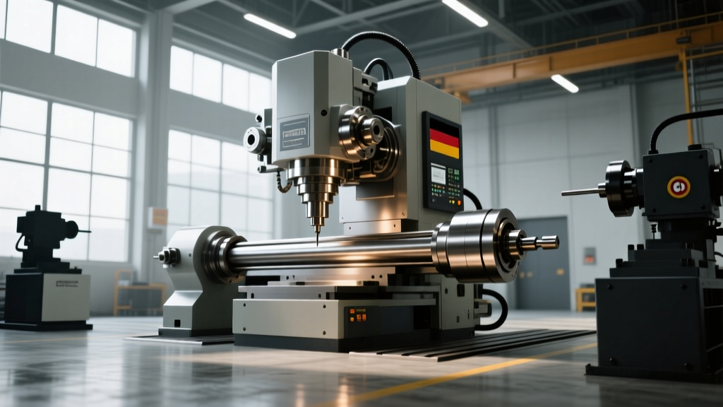
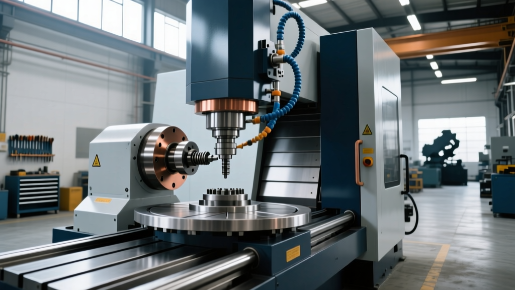
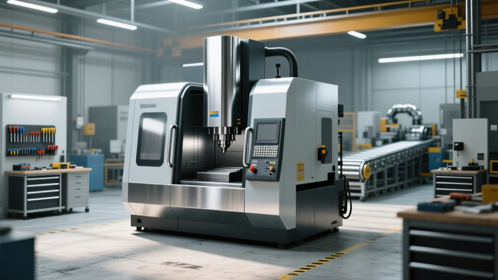
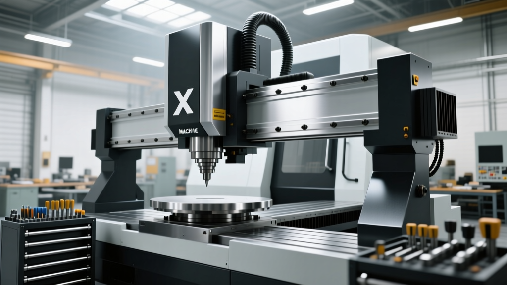
The architecture of the X machine 5 axis CNC represents a significant evolution in multi-axis machining center design, specifically engineered for high-speed, high-precision aerospace and medical component manufacturing. Unlike traditional 3-axis vertical machining centers (VMCs) retrofitted with add-on rotary tables, the X machine platform is built from the ground up with simultaneous 5-axis kinematics. This article dissects the technical specifications, drive mechanisms, and calibration protocols that define this platform, providing manufacturing engineers with the exact data needed to evaluate its capabilities for complex part production.
Core Architecture Snapshot: The X machine 5 axis CNC utilizes a modified trunnion configuration. The X and Z axes are driven by a moving column, the Y-axis is integrated into the fixed bed, and the B and C rotary axes are housed within a fully supported cradle table. This separation of heavy linear movements from rotary movements minimizes inertial mismatch during simultaneous contouring.Kinematic Configuration and X-Axis Linear Dynamics
The defining characteristic of the X machine 5 axis CNC is its X-axis drive system. While legacy machines rely on C3-grade ball screws, the X-axis on this platform is powered by a dual-sided synchronous linear motor. This eliminates mechanical backlash and provides a peak thrust force of 12,500 N, enabling rapid traverse rates of 60 m/min with a maximum acceleration of 1.5 G. Position feedback is managed by a Heidenhain LIP 48 absolute exposed linear scale with a 1-nanometer resolution. Because the scale is exposed, the machine requires a sealed, positive-pressure air purge system to prevent coolant mist and metallic swarf from contaminating the reading head. The linear motor primary coils are liquid-cooled via a dedicated chiller unit maintained at 20°C ± 0.1°C, preventing thermal expansion from altering the X-axis positioning accuracy, which holds a strict VDI/DGQ 3441 tolerance of ±0.002 mm over the full 1,000 mm travel.
Spindle Specifications and Tooling Interface
At the heart of the Z-axis column sits a 24,000 RPM motorized spindle utilizing an HSK-A63 tooling interface. The HSK-A63 taper provides superior radial rigidity and axial repeatability compared to CAT40/BT40 tapers, which is critical when executing 5-axis simultaneous toolpaths where side-loading forces fluctuate rapidly. The spindle rotor is supported by hybrid ceramic bearings featuring silicon nitride (Si3N4) balls. These ceramic balls are 40% lighter than steel, reducing centrifugal force at high RPMs and allowing for oil-air micro-lubrication rather than traditional grease packing. The spindle delivers 18 kW of continuous power (S1 duty) and peaks at 26 kW (S6 40% duty). To manage the thermal load generated at 24,000 RPM, the spindle housing features a helical cooling jacket connected to the primary chiller circuit, ensuring the spindle nose does not protrude more than 5 microns during a 4-hour warm-up cycle.
Tool Clamping and Retention Force
Tool retention is handled by a pneumatic-hydraulic drawbar system generating 18 kN of clamping force. For high-speed balancing, the tool changer utilizes a dual-arm cam mechanism that completes a tool-to-tool swap in 1.8 seconds. Tools must be balanced to ISO 1940-1 grade G2.5 at 24,000 RPM to prevent bearing degradation and maintain surface finish integrity.
Rotary Axis Drive Technologies: B and C Axes
The B and C axes dictate the machine's ability to maintain constant chip thickness and optimal cutting angles. The X machine 5 axis CNC employs a hybrid drive strategy for these axes, optimizing for both torque and speed.
| Axis | Drive Type | Continuous Torque | Peak Torque | Max Speed | Clamping Mechanism |
|---|---|---|---|---|---|
| B-Axis (Tilt) | Direct Drive (DD) Torque Motor | 850 Nm | 1,200 Nm | 100 RPM | Failsafe hydraulic disc brake |
| C-Axis (Rotary) | Roller Gear Cam (RGC) | 600 Nm | 950 Nm | 400 RPM | Pneumatic multi-disc clamp |
The B-axis utilizes a direct drive torque motor. This eliminates the mechanical transmission elements found in worm gear drives, resulting in zero backlash and exceptional dynamic response. This is vital for 3+2 indexing and rapid reorientation. Conversely, the C-axis uses a roller gear cam drive. While direct drive motors can suffer from torque ripple at very low speeds, the RGC mechanism provides perfectly smooth, zero-backlash continuous rotation at low RPMs, which is essential for helical interpolation and contouring operations on the C-axis. For further reading on optimizing 5-axis toolpaths and cutting angles, Sandvik Coromant's 5-axis machining guidelines provide excellent foundational strategies.
RTCP Calibration and Kinematic Verification
Rotary Tool Center Point (RTCP) functionality allows the CNC controller to dynamically adjust the linear axes (X, Y, Z) to compensate for the rotational movement of the B and C axes, keeping the tool tip precisely on the programmed path. Without accurate RTCP, simultaneous 5-axis machining is impossible. The X machine 5 axis CNC relies on the Heidenhain TNC 7 or Siemens Sinumerik ONE controllers to execute these complex kinematic transformations.
Standard RTCP Calibration Workflow
- Thermal Stabilization: Run the machine's automated warm-up cycle for 45 minutes to reach thermal equilibrium.
- Probe Measurement: Load the 3D touch probe and measure the fixed calibration sphere mounted on the machine bed to establish the baseline pivot point.
- Kinematic Cycle Execution: Execute the controller's native kinematic measurement cycle (e.g., Cycle 451 on Heidenhain). The machine will automatically tilt the B-axis to +90°, -90°, and rotate the C-axis through 360° to map geometric deviations.
- Data Compensation: The controller writes the calculated spatial errors into the kinematic data table, adjusting the virtual pivot point to match the physical machine geometry.
Verification of the RTCP calibration should be performed using a Renishaw AxiSet Check gauge or by machining a standardized NAS 979 circle-diamond-square test piece. According to ISO 10791-7, the maximum allowable deviation for the tool tip during a simultaneous 5-axis cone-frustum test is typically restricted to 0.015 mm for high-precision aerospace applications.
Thermal Displacement and Environmental Control
Five-axis machining centers are highly susceptible to thermal growth, which can ruin tight-tolerance parts. The X machine 5 axis CNC mitigates this through active thermal compensation algorithms. The machine is equipped with 14 PT100 temperature sensors strategically placed on the column, bed, spindle housing, and rotary table. The CNC controller samples these sensors every 100 milliseconds and applies real-time offset adjustments to the X, Y, and Z axes. For example, if the Y-axis ball screw generates 3°C of heat during a heavy roughing cycle, the controller calculates the expected thermal expansion based on the coefficient of thermal expansion for the specific cast iron alloy used in the bed, and preemptively shifts the Y-axis zero point by the exact micron deviation. Despite these software compensations, the machine must be installed in a climate-controlled facility maintained at 20°C ± 1°C to ensure the physical casting does not warp asymmetrically.
Troubleshooting Common Kinematic Errors
Even with advanced specifications, operational wear and environmental factors can introduce kinematic errors. Below is a diagnostic framework for addressing common surface finish and positioning issues on the X machine platform.
- Symptom: Scalloping or witness lines on spherical contours during simultaneous 5-axis finishing.
Cause: RTCP pivot length error or worn B-axis direct drive encoder.
Fix: Re-run the kinematic calibration cycle. If the error persists, check the B-axis absolute encoder readhead for contamination and verify the tool length measurement in the presetter. - Symptom: Chatter marks during heavy roughing in a 3+2 indexed position.
Cause: B-axis hydraulic brake failing to achieve full clamping pressure, allowing micro-movements under cutting loads.
Fix: Check the hydraulic clamping pressure gauge (must read minimum 120 bar). Inspect the brake friction pads for wear and replace if the thickness is below 2.0 mm. - Symptom: X-axis following error alarms during high-speed contouring.
Cause: Linear motor thermal overload or degraded cooling loop flow rate.
Fix: Verify the chiller unit flow rate is at least 15 liters per minute. Clean the chiller filter and ensure the coolant mixture is strictly 20% glycol to prevent algae buildup in the linear motor cooling jackets.
Mastering the technical nuances of the X machine 5 axis CNC requires moving beyond basic G-code programming and deeply understanding the electromechanical systems driving the kinematics. By maintaining strict adherence to thermal stabilization protocols, verifying RTCP data regularly, and monitoring the health of the direct drive and linear motor systems, manufacturing facilities can fully leverage this platform's capability to produce complex geometries with micron-level accuracy.