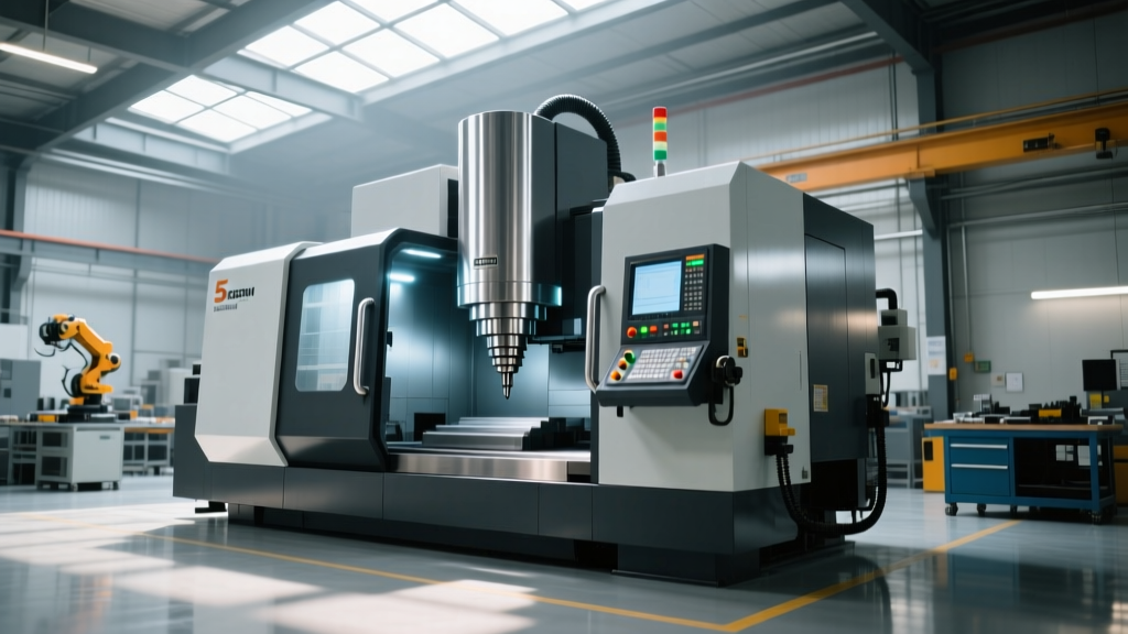
Using CNC Machining Center Technical Specifications to Optimize Setups
Learn how operators can interpret CNC machining center technical specifications to optimize setups, prevent crashes, and maximize tool life.
The Disconnect Between the Brochure and the Shop Floor
Most machine operators treat the equipment brochure as a document meant exclusively for the purchasing department or shop management. However, a deep understanding of CNC machining center technical specifications is one of the most underutilized tools for preventing crashes, extending tool life, and holding tight tolerances. When an operator understands the mechanical and electrical limitations defined in the spec sheet, they can adjust feeds, speeds, and setups to work in harmony with the machine's actual physical capabilities rather than fighting against them.
This guide translates raw engineering specifications into actionable, shop-floor best practices for VMC and HMC operators.
⚠️ The 'Max Spec' Trap
Never program a machine based on its 'Maximum' listed specifications. A spec sheet listing a 'Max Rapid Traverse' of 48 m/min (1,890 ipm) does not mean the machine can accurately contour at that speed. Similarly, 'Max Spindle RPM' is often achievable only with reduced torque and requires specific high-speed toolholder balancing (e.g., G2.5 at 25,000 RPM). Always base your cutting parameters on continuous duty ratings and cutting feed limits.
Decoding Spindle and Axis Drive Specifications
The spindle is the heart of the machining center, but peak horsepower is a misleading metric for daily operations. Operators must look at the torque curve and the continuous duty rating.
Torque Curve Application in Roughing vs. Finishing
A standard 40-taper vertical machining center might advertise 30 peak horsepower. However, the technical specifications will reveal that this peak is only achieved at higher RPMs (e.g., 6,000 RPM). At 1,000 RPM, that same spindle might only produce 122 Nm (90 ft-lbs) of torque.
- The Failure Mode: If an operator programs a 3-inch indexable face mill to rough at 600 RPM with a heavy depth of cut, the spindle will stall, or the drive will trigger an overcurrent alarm, regardless of the '30 HP' sticker on the machine guard.
- The Best Practice: Match your roughing RPM to the machine's peak torque band. For standard 40-taper machines, this is typically between 2,500 and 3,500 RPM. Reserve high RPMs strictly for finishing passes with low radial engagement.
Axis Drives: Rapids vs. Cutting Feed Rates
Technical specifications usually highlight rapid traverse rates (e.g., 35.6 m/min). However, for 3D contouring or high-speed machining (HSM), the maximum cutting feed rate and the servo motor torque are what dictate surface finish and accuracy. High servo torque allows the axis to rapidly decelerate and reverse direction during tight cornering without 'dog-boning' or leaving dwell marks on the part.
Tool Changer and Work Envelope Limitations
Automatic Tool Changer (ATC) specifications are frequently ignored until a tool drops on the shop floor or the carousel faults. Understanding the difference between maximum tool weight and maximum tool moment is critical for safe setups.
| Spec Sheet Metric | What It Actually Means | Operator Action & Best Practice |
|---|---|---|
| Max Tool Weight (e.g., 7 kg / 15.5 lbs) | The absolute maximum mass a single pocket can hold. | If using a heavy roughing tool, ensure the adjacent pockets are empty to prevent carousel imbalance and excessive wear on the ATC cam arm. |
| Max Tool Moment (e.g., 12 Nm) | The rotational force exerted by a long, heavy tool extending far from the spindle face. | A 300mm long boring bar might weigh only 5 kg, but its length creates a moment that exceeds the ATC arm's lifting capacity. Keep heavy, long tools in the main spindle, not the magazine. |
| Max Tool Diameter (with/without adjacent tools) | Physical clearance in the magazine carousel. | Always check the 'with adjacent tools' spec. A 100mm face mill requires empty pockets on both sides to rotate safely without colliding with neighboring toolholders. |
| Z-Axis Travel & Spindle Nose to Table | True vertical working envelope. | Subtract the gauge length of your longest tool and the height of your vise/fixture. Ensure you have at least 50mm of clearance for safe Z-axis retraction and tool changes. |
Coolant Pressure and Chip Evacuation Specs
Coolant specifications are often listed as a simple 'Yes/No' for Through-Spindle Coolant (TSC), but the bar pressure rating dictates what tooling you can actually run effectively. According to Sandvik Coromant's Metal Cutting Knowledge, proper coolant pressure is the primary variable in preventing chip welding and tool breakage in deep-cavity milling and drilling.
Matching TSC Pressure to Tooling Requirements
- 20 Bar (290 PSI): Standard for general flood cooling, tapping, and shallow end milling. It is insufficient for clearing chips from deep cavities.
- 70 Bar (1,000 PSI): The minimum requirement for carbide gun drills and deep-hole boring (L/D ratios exceeding 10:1). The high pressure is required to force chips up the narrow flutes. Running a gun drill at 20 bar will result in packed flutes, tool snapping, and scrapped parts.
- 150+ Bar (2,100+ PSI): Required for specialized high-pressure coolant (HPC) turning and machining aerospace superalloys like Inconel, where the pressure is used to mechanically break the chip at the cutting edge.
Operator Tip: If your machine spec sheet lists a 20-bar TSC pump, do not attempt to program deep-hole peck drilling cycles with gun drills. Switch to parabolic flute twist drills or outsource the deep-hole operation to a machine with 70+ bar capabilities.
Thermal Stability and Positioning Accuracy
Accuracy specifications are governed by international standards, most notably ISO 230-2 standards for machine tool calibration. However, operators must understand the difference between positioning accuracy and repeatability, and how thermal growth affects both.
'A machine might boast a positioning accuracy of ±0.005mm, but that spec is measured in a climate-controlled environment at 20°C (68°F) after a standardized warm-up cycle. On the shop floor, friction from the ballscrews and spindle bearings generates heat, causing the axis to physically expand.'
Managing Thermal Growth on the Shop Floor
A standard 32mm pitch ballscrew on a 1-meter Y-axis can expand up to 0.025mm (0.001 inches) during the first 45 minutes of operation as it reaches thermal equilibrium. If an operator loads raw material and begins machining tight-tolerance bores immediately upon powering on the machine, the first three parts will likely be out of spec due to Z-axis and X/Y-axis thermal drift.
The Best Practice: Implement a mandatory 15-to-20-minute macro warm-up program every morning. This program should run the spindle at varying RPMs (from 1,000 to max RPM) and stroke all linear axes to 75% of their travel limits. This stabilizes the machine's thermal state before the first critical cut is made.
Quick Reference: Operator Pre-Flight Checklist Based on Specs
Before running a new program or setting up a complex fixture, operators should cross-reference their setup against the machine's technical specifications using this checklist:
- Verify Tool Moments: Calculate the gauge length and weight of all tools in the carousel. Ensure no single tool exceeds the ATC's maximum moment rating.
- Check RPM vs. Torque: Confirm that roughing operations are programmed within the spindle's peak torque band, not just its peak horsepower band.
- Validate TSC Pressure: Ensure the programmed deep-hole drilling tools match the machine's installed TSC pump pressure (e.g., do not use 70-bar gun drills on a 20-bar system).
- Confirm Contouring Feed Rates: Check the spec sheet for 'Max Cutting Feed Rate' (which is always lower than 'Max Rapid Traverse') to ensure 3D contouring programs won't trigger feedrate clamping alarms.
- Clearance Check: Measure the distance from the spindle nose to the top of the workpiece in the vise, and ensure the Z-axis travel spec allows for safe tool clearance during ATC swaps.
By shifting the perspective of CNC machining center technical specifications from a purchasing checklist to a daily operational manual, shops can drastically reduce unplanned downtime, eliminate scrap caused by thermal drift, and maximize the return on their capital equipment investments. For further reading on optimizing machining parameters, consult the technical archives at Modern Machine Shop.