Troubleshooting RTCP Errors on a CNC Machine 5 Axis Setup
Learn how to diagnose and fix RTCP errors, kinematic drift, and thermal growth on your CNC machine 5 axis setup to prevent crashes and scrap parts.
The True Cost of 5-Axis Kinematic Drift
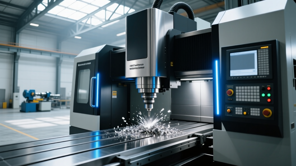
When operating a cnc machine 5 axis configuration, the margin for error is measured in microns. Unlike standard 3-axis vertical machining centers, 5-axis trunnion and swivel-head machines rely on complex kinematic chains. If the Rotated Tool Center Point (RTCP) data is misaligned by even 0.0005 inches (12.7 microns), the controller will miscalculate the tool tip's position during simultaneous A and C axis interpolation. The result is not just a scrapped aerospace impeller or medical implant; it is often a catastrophic spindle crash.
Replacing a high-frequency 20,000 RPM spindle on a machine like the Haas UMC-750SS or DMG MORI DMU 50 3rd Gen costs between $18,000 and $32,000, not including the 4-to-8 weeks of downtime. Understanding how to troubleshoot and recalibrate your machine's kinematic parameters is a mandatory skill for 5-axis technicians.
⚠️ CRITICAL WARNING: Never bypass RTCP limits or disable G43.4/TRAORI commands to 'force' a program to run when encountering following errors. Disabling tool center point control while the rotary axes are commanded to move will cause the tool to plunge directly into the workpiece or machine table.Diagnostic Matrix: Symptom to Root Cause
Before tearing into the machine geometry, use this diagnostic matrix to isolate whether your 5-axis deviation is mechanical, thermal, or software-driven. Data synthesized from Haas Automation's technical library and industry metrology standards points to these primary failure modes.
| Symptom / Alarm | Controller Code | Root Cause | Calibration Fix |
|---|---|---|---|
| Tool marks on part during A-axis tilt | N/A (Visual) | Trunnion table Y-axis offset drift | Run APC (Automatic Part Centerline) probe cycle |
| Excessive Following Error | Haas Alarm 109 / Fanuc 411 | Rotary axis mechanical binding or servo lag | Check worm gear backlash and adjust servo gains |
| Z-depth varies as C-axis rotates | N/A (Measured) | Spindle head nod (pitch error) or C-axis face runout | Map kinematic pitch/yaw errors in macro variables |
| Tool vector misalignment | Siemens Alarm 20094 | Post-processor outputting incorrect I,J,K vectors | Verify CAM post for exact machine kinematic model |
Step-by-Step Trunnion Table Re-Calibration
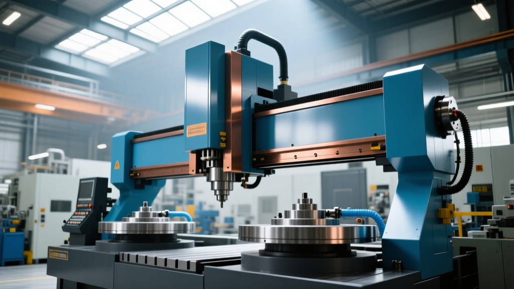
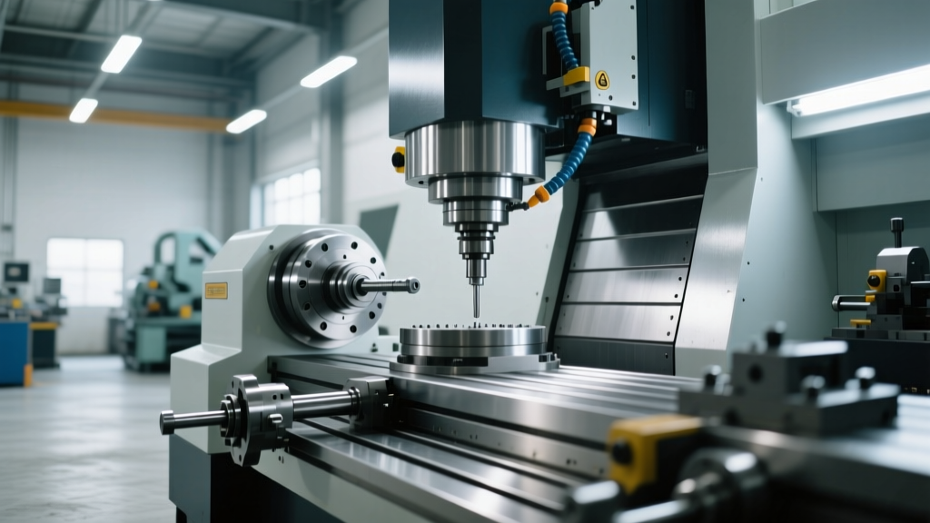
If your diagnostic points to trunnion drift—a common issue after heavy roughing cycles or minor crashes on the B or C axis—you must recalibrate the center of rotation. This procedure assumes the use of a spindle-mounted touch probe, such as the Renishaw OMP60 or Haas WIPS.
- Prep the Calibration Artifact: Mount a precision ground calibration sphere (typically 1.5000 inch / 38.1mm diameter) on the trunnion table. Ensure the artifact is positioned at least 4 inches off-center from the C-axis centerline to maximize leverage during rotational measurement.
- Establish Baseline Z: Command the machine to probe the top of the sphere at A0, C0. Record the exact Z-coordinate. This establishes your baseline tool length offset relative to the rotary center.
- Execute the A-Axis Tilt Cycle: Command an A90 tilt. The probe will now approach the sphere from the side. The machine's macro (e.g., Haas Macro 9024) will probe the sphere to find its new center in the Y and Z planes.
- Calculate the Deviation: The controller compares the theoretical sphere center based on the current kinematic parameters against the actual probed center. If the Y-deviation exceeds 0.0004 inches, the macro will automatically update the Y-axis rotary offset parameter (e.g., Parameter 12404 on Fanuc/Robodrill or specific NGC settings on Haas).
- Verify with Ballbar: For high-precision aerospace work, follow up the probe cycle with a wireless telescoping ballbar test (like the Renishaw QC20-W, priced around $22,000). Run a 100mm radius circular test in the XZ plane to verify that the volumetric error remains under 20 microns across the full rotary sweep.
Thermal Management in Modern Machine Environments
A frequently overlooked cause of RTCP failure on a cnc machine 5 axis mill is asymmetric thermal growth. According to research published via the Modern Machine Shop technical archives, thermal distortion accounts for up to 70% of dimensional errors in multi-axis machining.
Coolant and Ambient Variables
C-frame 5-axis machines are particularly susceptible to ambient temperature shifts. If your shop floor drops by just 4°F (2.2°C) overnight, the cast iron column will contract differently than the trunnion base. By the morning shift, the Z-axis to A-axis centerline distance may have shifted by 15 to 25 microns.
- Implementation of Warm-Up Macros: Never start a tight-tolerance 5-axis part cold. Program a 15-minute warm-up macro that cycles the X, Y, and Z axes at 50% rapid rates and oscillates the A and C axes through their full ranges. This distributes friction-induced heat evenly through the thrust bearings and worm drives.
- Spindle Cooling Jackets: Verify the flow rate of your spindle chiller unit. A drop below 2.5 GPM in the chiller circuit will cause the spindle housing to expand outward, altering the tool tip position relative to the A-axis pivot point. Clean the chiller reservoir filters every 90 days to prevent flow restriction.
Post-Processor Verification for G43.4 and TRAORI
Mechanical perfection means nothing if the G-code is misinterpreted. The controller must know exactly where the tool tip is relative to the rotary pivot points at every millisecond of the cut.
For Fanuc and Haas controls, G43.4 activates the Tool Center Point Control mode. If your CAM post-processor is outdated and outputs standard G43 (Tool Length Compensation) alongside rotary moves, the machine will lock the tool vector in the Z-axis direction. As the A-axis tilts, the tool tip will swing in an arc, gouging the part.
💡 Expert Tip: Siemens controllers use the TRAORI (Transformation Orientation) command instead of G43.4. When setting up a new Siemens-based 5-axis machine (like a DMG MORI monoBLOCK), ensure your post-processor is explicitly configured to output TRAORI at the start of the program and TRACOMP/TRAFOOF at the end of the operation. Failing to cancel TRAORI before tool changes will result in the tool changer crashing into the spindle housing.When to Call the OEM Service Technician
While in-house maintenance teams can handle probe recalibrations and thermal management, certain kinematic failures require OEM intervention. If your ballbar diagnostic reveals cyclic errors that repeat exactly every 360 degrees of C-axis rotation, you likely have a physical runout issue in the C-axis face gear or a warped encoder scale. Repairing the internal rotary union and replacing the Heidenhain or Fanuc absolute encoders requires laser interferometer calibration that costs between $3,500 and $6,000 per day. For deep mechanical teardowns, consult the Sandvik Coromant milling knowledge base for cutting force data to ensure your feed rates aren't exceeding the rotary table's maximum clamping torque, which accelerates gear wear and necessitates premature OEM rebuilds.