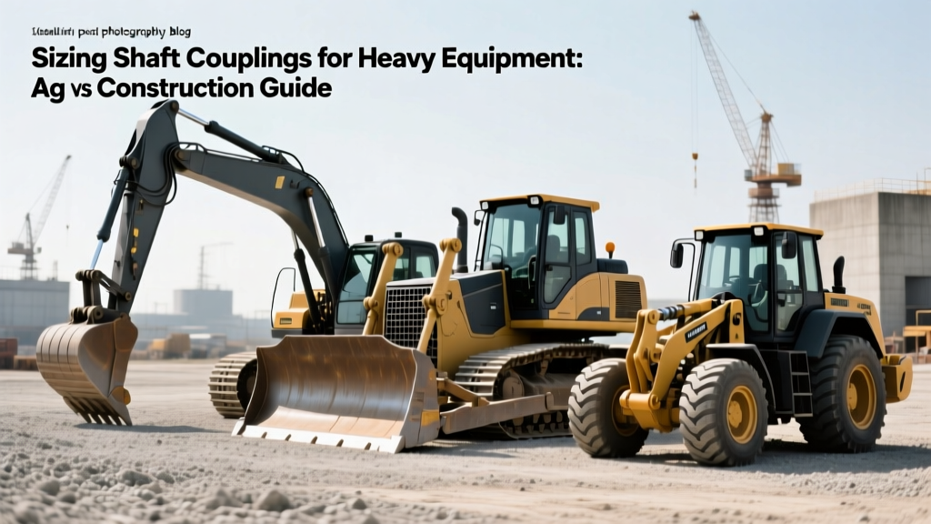
Sizing Shaft Couplings for Heavy Equipment: Ag vs Construction Guide
Master the engineering principles of sizing shaft couplings for heavy equipment. Compare torque, misalignment, and shock loads in ag vs construction machinery.
The Physics of Power Transmission: Why Sector Dictates Sizing
When engineers approach the task of sizing shaft couplings for heavy equipment, the fundamental equation remains constant: Design Torque (Td) equals Nominal Torque (Tn) multiplied by the Service Factor (Sf). However, applying this formula uniformly across agricultural and construction machinery is a critical engineering error. The operational profiles, structural deflection characteristics, and torsional vibration signatures of a Class 8 combine harvester differ radically from those of a 30-ton hydraulic excavator.
While both sectors demand extreme durability, the nature of the mechanical stress varies. Agricultural drivetrains are defined by high-inertia shock loads and severe torsional vibration from low-RPM diesel engines. Construction drivetrains are defined by continuous high-torque demands, extreme structural chassis flex, and precise hydraulic pump alignment. Understanding these distinctions is mandatory for preventing catastrophic driveline failures.
Core Sizing Equation:Td = Tn × Sf
Where Tn = (HP × 5252) / RPM (in lb-ft) or (kW × 9550) / RPM (in Nm).
The Service Factor (Sf) is where agricultural and construction applications diverge most drastically.
Agricultural Heavy Equipment: Shock Loads and PTO Dynamics
Agricultural machinery, particularly tractors and harvesting equipment, relies heavily on Power Take-Off (PTO) systems and variable-speed mechanical drives. According to standards maintained by the American Society of Agricultural and Biological Engineers (ASABE), standard PTO shafts operate at either 540 RPM (1.75-inch 6-spline) or 1000 RPM (1.375-inch 21-spline). Sizing couplings for these systems requires accounting for the extreme torsional vibration inherent in agricultural diesel engines and the sudden shock loads of engaging ground-driven implements.
Sizing for High-Inertia Implement Engagement
When a tractor operator engages a heavy rotary cutter or a round baler at 1000 RPM, the driven implement's inertia creates a transient torque spike. This spike can momentarily exceed 300% of the nominal running torque. If the coupling is sized only for continuous running torque, the elastomeric elements will instantly shear or overheat due to hysteresis.
- Coupling Type Selection: Polyurethane jaw couplings (spider type) or elastomeric tire couplings are standard. They provide the necessary torsional damping to absorb engine firing pulses and protect the gearbox.
- Service Factor (Sf): Typically ranges from 2.0 to 3.0 for PTO drives, depending on the driven implement's inertia and the frequency of engagement.
- Misalignment Tolerance: Agricultural implements are frequently hitched and unhitched, leading to high angular misalignment (up to 3 degrees) and significant axial displacement during operation over uneven terrain.
Construction Machinery: Continuous Torque and Chassis Flex
Construction equipment, such as excavators, bulldozers, and wheel loaders, utilizes hydrostatic drives, swing mechanisms, and heavy final drives. The primary challenge in sizing shaft couplings for heavy equipment in this sector is not necessarily sudden shock loading, but rather continuous high torque combined with severe mainframe deflection.
Track Drives and Hydraulic Pump Sizing
In a typical 20-ton excavator, the main hydraulic pump is mounted directly to the engine flywheel housing, while secondary pumps or swing motors may be located further along the chassis. When the boom is fully extended and loaded with dense material, the excavator's mainframe physically twists. This structural deflection induces parallel and angular misalignment between the pump drive and the engine.
According to SKF coupling engineering guidelines, metallic couplings are often required here to handle the continuous torque without the degradation associated with elastomeric hysteresis under constant heavy load.
- Coupling Type Selection: Grid couplings (e.g., Falk Steelflex) or fully lubricated gear couplings. These provide high torsional stiffness and accommodate chassis flex without generating destructive restorative forces on the pump bearings.
- Service Factor (Sf): Generally lower than Ag applications, typically 1.5 to 2.0, because hydraulic systems inherently cushion shock loads via relief valves and fluid compressibility.
- Misalignment Tolerance: Grid couplings can accommodate up to 0.25 degrees of angular misalignment and 0.15 inches of parallel offset, which perfectly matches the deflection profile of heavy earthmoving chassis.
Comparative Matrix: Ag vs. Construction Sizing Parameters
The following table illustrates how the technical specifications diverge when sizing shaft couplings for heavy equipment across these two distinct sectors.
| Parameter | Agricultural (e.g., Combine Rotor Drive) | Construction (e.g., Excavator Swing Drive) |
|---|---|---|
| Primary Load Profile | High shock, high transient spikes, torsional vibration | Continuous high torque, steady-state with hydraulic damping |
| Typical Service Factor (Sf) | 2.0 – 3.5 | 1.5 – 2.0 |
| Preferred Coupling Type | Elastomeric Tire, Polyurethane Jaw | Lubricated Gear, Steel Grid |
| Misalignment Source | Implement hitch articulation, uneven field terrain | Mainframe structural deflection under boom load |
| Environmental Threat | Organic dust, crop moisture, UV degradation of elastomers | Abrasive silica dust, high-pressure washdowns, grease washout |
Real-World Sizing Walkthrough: The Math in Practice
To demonstrate why sector context matters, consider two machines with identical engine outputs but vastly different coupling requirements.
Scenario A: 150 HP Agricultural Tractor (PTO Drive)
The tractor operates a heavy-duty flail mower at 1000 RPM. The mower blades frequently strike hidden rocks and dense brush.
- Nominal Torque (Tn): (150 HP × 5252) / 1000 RPM = 787.8 lb-ft.
- Service Factor (Sf): Due to the high inertia of the flail drum and severe shock loads from striking debris, an Sf of 3.0 is mandated.
- Design Torque (Td): 787.8 × 3.0 = 2,363.4 lb-ft.
- Selection: The engineer must select a heavy-duty elastomeric coupling rated for a minimum of 2,400 lb-ft, featuring a high-durometer polyurethane spider to resist extrusion under shock loads.
Scenario B: 150 HP Excavator (Hydraulic Pump Drive)
The excavator drives a variable-displacement axial piston pump at 2000 RPM to power the boom and stick cylinders.
- Nominal Torque (Tn): (150 HP × 5252) / 2000 RPM = 393.9 lb-ft.
- Service Factor (Sf): The hydraulic system absorbs shock via relief valves. The load is continuous and steady. An Sf of 1.5 is appropriate.
- Design Torque (Td): 393.9 × 1.5 = 590.8 lb-ft.
- Selection: The engineer selects a steel grid coupling rated for 600 lb-ft. Despite the identical engine horsepower, the construction coupling is physically smaller and rated for less than half the design torque of the agricultural coupling, but it is engineered to handle constant high-speed rotation and chassis misalignment.
Engineering Insight: Horsepower alone is a misleading metric for coupling sizing. The combination of operating RPM and sector-specific Service Factors dictates the physical dimensions and material science of the coupling. A low-RPM, high-shock Ag application will always demand a physically larger, more robust coupling than a high-RPM, hydraulically damped construction application of the exact same horsepower.
Environmental Sealing and Material Degradation
The final variable in sizing shaft couplings for heavy equipment is the operating environment, which dictates material selection and sealing requirements.
Agricultural Degradation Factors
In agricultural applications, elastomeric couplings are exposed to organic dust, crop sap, and high UV radiation. Standard rubber elements will dry-rot and crack within a single harvesting season if exposed to direct sunlight and ozone. Engineers must specify EPDM (Ethylene Propylene Diene Monomer) or specialized polyurethane compounds that resist UV degradation and chemical breakdown from agricultural fertilizers and pesticides. Furthermore, PTO shaft couplings require telescoping guards to prevent crop wrapping, which can generate extreme axial pull-out forces on the coupling hubs.
Construction Degradation Factors
Construction environments are dominated by abrasive silica dust and high-pressure water ingress during daily equipment washdowns. For gear and grid couplings, the primary failure mode is not material fatigue, but lubrication failure. Silica dust penetrating the coupling seal mixes with the grease, creating a lapping compound that rapidly destroys the gear teeth or grid slots. Sizing for construction requires specifying labyrinth seals or Viton lip seals designed to exclude fine particulate matter, and mandating the use of high-tack, molybdenum-disulfide (MoS2) fortified greases that resist water washout.
Summary Framework for Cross-Sector Specification
When specifying couplings across mixed fleets or designing multi-purpose power units, follow this decision tree:
- If the driven load is mechanical, high-inertia, and subject to impact (Ag): Prioritize torsional damping. Calculate Td using an Sf of 2.5+. Select elastomeric or jaw couplings. Verify UV and chemical resistance of the flexible element.
- If the driven load is fluid/hydraulic, continuous, and subject to frame twist (Construction): Prioritize misalignment capacity and torsional stiffness. Calculate Td using an Sf of 1.5 to 2.0. Select grid or gear couplings. Specify labyrinth sealing and heavy-duty grease retention.
By respecting the distinct mechanical realities of agricultural shock loads versus construction chassis deflection, engineers can eliminate premature driveline failures and optimize power transmission efficiency across the heavy equipment spectrum.