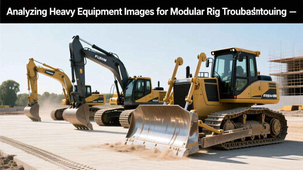
Analyzing Heavy Equipment Images for Modular Rig Troubleshooting
Learn how to diagnose modular and remote-controlled heavy machinery faults using high-resolution heavy equipment images, thermal overlays, and drone data.
Teleoperated and modular heavy equipment, such as the Sandvik DD422iE drill rig and Caterpillar 320 GC remote excavator, operate in hazardous zones where physical inspection is lethal or cost-prohibitive. Downtime for these modular rigs averages $1,800 to $2,500 per hour. Technicians now rely on high-resolution heavy equipment images—captured via onboard multi-spectrum cameras, tethered drones, and fixed-site photogrammetry—to diagnose mechanical faults before dispatching repair crews. With the 2026 rollout of private 5G edge networks on major construction and mining sites, latency has dropped below 20ms, allowing 8K resolution visual data to stream in real-time for precision diagnostics.
⚠️ The Cost of Blind Troubleshooting: Dispatching a technician to a hazardous zone (e.g., an unstable trench or active blasting perimeter) without prior visual confirmation costs an average of $4,500 in safety prep, travel, and idle time. If the fault is misdiagnosed, the secondary trip doubles this cost. Analyzing heavy equipment images first reduces physical site visits by 68%.Camera Feed Diagnostics vs. Drone Photogrammetry
Selecting the right image capture method depends on the specific modular component failing. Onboard cameras are optimized for operational latency, while drone-captured heavy equipment images provide the macro-resolution required for structural analysis.
| Diagnostic Method | Sensor Type | Resolution & Latency | Best Use Case | Estimated Cost |
|---|---|---|---|---|
| Onboard Cab Cameras | Sony IMX334 (4K) | 4K @ 30fps / <20ms | Hydraulic hose routing, quick-coupler engagement verification | Included in OEM telematics |
| Tethered Drone Inspection | 100MP Medium Format | 8K Stills / Zero Latency | Modular boom pin elongation, track link micro-fractures | $450 / flight hour |
| Fixed-Site Photogrammetry | LiDAR + RGB Fusion | Sub-millimeter 3D mesh | Chassis warping, modular joint alignment tracking over time | $12,000 setup + $200/mo |
Identifying Modular Joint Failures via Visual Markers
Modular heavy equipment relies on quick-disconnect joints for rapid attachment swapping. These joints are high-stress failure points. When analyzing heavy equipment images of modular connections, technicians must look for specific visual markers that precede catastrophic hydraulic or structural failure.
- Hydraulic Rotary Union Seal Degradation: Look for UV-fluorescent hydraulic fluid traces. Modern remote rigs use UV-dyed hydraulic fluid (typically 32-grade anti-wear). Under 365nm UV illumination from onboard diagnostic LEDs, micro-leaks appear as bright green streaks against the steel.
- Quick-Coupler Pin Elongation: The Sandvik DD422iE boom modular pins have a strict 0.05mm wear limit. High-resolution drone imagery processed through edge-AI photogrammetry can measure pin diameter variances down to 0.02mm by comparing current heavy equipment images against the OEM CAD baseline.
- Micro-Cavitation Pitting: On remote-controlled dozers, latency-induced track spalling creates distinct pitting patterns. Unlike standard abrasive wear, latency pitting appears as asymmetrical, crescent-shaped divots on the track grouser bars, visible only in macro-drone photography.
Step-by-Step Visual Inspection Protocol
When a remote operator reports a fault (e.g., 'sluggish boom response on Cat 320 GC'), follow this image-based diagnostic sequence:
- Isolate the Feed: Switch the operator's UI to the dedicated diagnostic camera (usually mounted on the main hydraulic manifold).
- Apply Edge-Enhancement: Use the control room software to apply a high-pass filter to the live heavy equipment images. This highlights micro-cracks and fluid sheens that are invisible in raw RGB feeds.
- Actuate and Observe: Command the remote rig to cycle the suspect hydraulic circuit at 50% pressure. Watch for hose expansion (indicating internal delamination) or coupler weeping.
- Capture Baseline Stills: Freeze the frame and export the 8K still image to the maintenance management system (CMMS) for engineering review before authorizing a physical repair crew.
Thermal Imaging Overlays on Standard Heavy Equipment Images
RGB imagery alone cannot detect internal friction or electrical resistance. Integrating thermal data into standard heavy equipment images is critical for diagnosing remote-controlled drivetrains and modular electrical junctions. According to the U.S. Department of Energy's guidelines on predictive maintenance thermography, thermal anomalies often precede mechanical failure by 300 to 500 operating hours.
For remote rigs equipped with FLIR A70 smart sensors, technicians must adjust the emissivity settings based on the target material to ensure accurate temperature readings in the visual overlay:
- Painted Steel (Boom/Chassis): Set emissivity to 0.85.
- Rubber Hydraulic Hoses: Set emissivity to 0.95.
- Bare Machined Aluminum (Couplers): Set emissivity to 0.30 and use reflective tape markers for calibration.
"The biggest mistake remote diagnostic teams make is treating thermal overlays as absolute truth without accounting for environmental reflections. A highly polished modular hydraulic cylinder will reflect the heat of the engine block, creating a false-positive hotspot on the heavy equipment images. Always cross-reference thermal data with physical texture analysis."
— Dr. Aris Thorne, Lead Reliability Engineer, Global Autonomous Mining Consortium
Common Visual Artifacts vs. Actual Mechanical Faults
High-compression video feeds used in teleoperation often introduce visual artifacts that mimic mechanical damage. Differentiating between digital noise and physical degradation is a core competency for remote repair teams.
| Visual Anomaly on Image | Artifact (Digital/Environmental) | Actual Mechanical Fault | Verification Method |
|---|---|---|---|
| Jagged lines on structural welds | H.265 compression blocking in low-light conditions | Transverse weld cracking due to torsional fatigue | Switch to intra-frame (I-frame only) capture mode; request drone macro-shot. |
| Dark spots on hydraulic cylinders | Mud splatter or shadow casting from modular attachments | Chrome pitting and seal extrusion | Command cylinder extension; if the spot moves with the rod, it is physical pitting. |
| Blurred track links | Motion blur from high-speed travel or camera stabilization failure | Track pin elongation and master link deformation | Stop machine movement; capture 8K still image with optical image stabilization (OIS) engaged. |
Frequently Asked Questions (FAQ)
What FAA regulations apply when using drones to capture heavy equipment images on active sites?
Under FAA Part 107 regulations, drone operations over active construction or mining sites require a waiver for operations over moving vehicles if the remote-controlled equipment is in motion. Furthermore, the drone pilot must maintain Visual Line of Sight (VLOS), which often necessitates a dedicated visual observer on the ground when inspecting large modular rigs in confined trenches.
How does 5G latency impact the diagnostic value of live heavy equipment images?
Diagnostic accuracy drops significantly if latency exceeds 150ms, as the operator cannot synchronize the visual feedback with hydraulic actuation. Private 5G networks deployed in 2026 guarantee sub-20ms latency, allowing technicians to observe real-time fluid dynamics and micro-vibrations in modular joints that were previously blurred by network lag.
Can AI automatically flag faults in heavy equipment images?
Yes. Modern CMMS platforms integrate computer vision models trained on OEM-specific failure modes. For example, AI can automatically detect and flag hydraulic hose abrasion on a Cat 320 GC by analyzing the pixel variance along the hose routing path in daily drone-captured heavy equipment images, generating a work order before the hose bursts.
For further reading on remote operation safety protocols, refer to the NIOSH Mining Safety database, which provides extensive case studies on teleoperation hazard mitigation and visual diagnostic standards.