Heavy Equipment Ramps for Wind Farm Construction: Technical Specs and Load Dynamics
Analyze heavy equipment ramps for renewable energy construction. Explore technical specs, load dynamics, and deployment protocols for wind and solar sites.
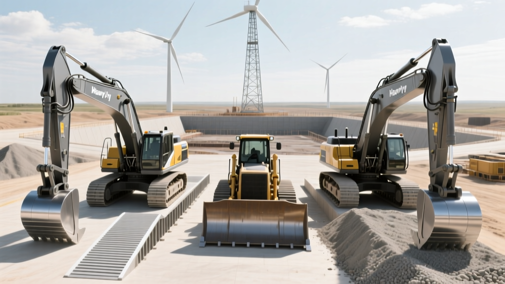
Deploying heavy machinery to renewable energy sites requires overcoming severe logistical bottlenecks. Wind farms and utility-scale solar arrays are frequently located on unprepared, uneven terrain with soft soil bearing capacities. Moving 60-ton mobile cranes, rotary drilling rigs, and large excavators onto lowboy trailers or across deep cable trenches demands specialized loading solutions. Heavy equipment ramps engineered for renewable energy construction must withstand extreme point loads, dynamic impact forces, and harsh environmental degradation. This technical guide dissects the metallurgical specifications, load distribution physics, and deployment protocols required for safe ramp operations in wind and solar logistics.
The Engineering Challenge: Point Loads on Unprepared Terrain
Unlike standard highway loading docks, renewable energy sites lack reinforced concrete aprons. When a Liebherr LTM 1300-6.2 mobile crane or a Bauer BG 28 rotary drilling rig transitions from compacted gravel to a ramp system, the ground bearing pressure shifts drastically. The primary failure vector in these scenarios is not the ramp snapping, but the ramp's landing plate punching through the soft topsoil, causing a catastrophic lateral slip.
⚠️ CRITICAL WARNING: Ground Bearing Pressure (GBP)Never deploy heavy equipment ramps directly on uncompacted topsoil. OSHA 1926.602 mandates that loading surfaces must support the maximum intended load without yielding. For a 120,000 lb crane on a 4-axle lowboy, the ramp landing zone must be reinforced with timber mats or compacted aggregate to achieve a minimum GBP of 4,500 PSF (pounds per square foot) to prevent punch-through failure.
Metallurgical Specifications: 6061-T6 Aluminum vs. A572 Steel
The selection of ramp material dictates the weight-to-capacity ratio, which is critical when transport logistics require loading and unloading ramps daily across vast wind farm leases. Below is a technical comparison of the two primary alloys used in heavy-duty renewable energy ramp systems.
| Specification | 6061-T6 Aluminum (Modular Track) | A572 Grade 50 Steel (Trench Span) |
|---|---|---|
| Yield Strength | 40,000 PSI | 50,000 PSI |
| Max Axle Load (Pair) | 32,000 lbs | 60,000 lbs |
| Weight per 10ft Section | 85 lbs | 310 lbs |
| Traction Profile | Extruded serrated rungs | Welded diamond plate / grating |
| 2026 Market Cost (Pair) | $5,800 - $7,200 | $14,500 - $18,000 |
Deflection Mathematics and Bending Stress
When evaluating heavy equipment ramps for wind turbine component transport, engineers must calculate the bending stress on the ramp rungs. Consider a Cat 336 excavator with 13,350 lbs resting on a single tire. If the tire contact patch is 10 inches long and rests entirely on a single 3-inch wide aluminum rung, the localized bearing stress is 445 PSI. While this is well below the 40,000 PSI yield strength of 6061-T6 aluminum in pure compression, the rung acts as a simply supported beam spanning 12 inches between the main rails.
Using the bending stress formula σ = (M × c) / I, where the bending moment (M) peaks at the center of the rung, the tensile stress on the bottom flange of the extruded rung can reach 18,000 PSI under dynamic loading. This leaves a safety factor of roughly 2.2, which is the industry minimum for mobile construction loading operations. According to the OSHA 1926.602 material handling standards, any ramp system exhibiting permanent plastic deformation (a visible sag in the rungs) must be immediately removed from service.
Dynamic Impact Factors (EIF) During Loading Operations
Static weight ratings are insufficient for renewable energy logistics. When a loaded water truck or a piling rig ascends a 15% grade ramp and applies the brakes, the dynamic force shifts the center of gravity forward, increasing the load on the front axle and the ramp hinges. This is quantified as the Equipment Impact Factor (EIF).
- Smooth Acceleration/Deceleration: EIF of 1.1 to 1.2 (10-20% increase in static load).
- Hard Braking on 15% Grade: EIF of 1.4 to 1.6 (40-60% increase in static load on the lower ramp hinges).
- Dropping off a Lip/Transition Plate: EIF of 2.0+ (Shock loading that can instantly shear aluminum hinge pins).
To mitigate EIF shock loading on wind sites, operators must use ramps with a minimum 14-inch wide transition plate at the truck bed interface, and the equipment operator must maintain a crawl speed of less than 2 MPH during the transition phase.
Deployment Protocol: Bridging Cable Trenches on Solar Arrays
Utility-scale solar farms require thousands of feet of underground medium-voltage cable trenches. Crossing these 3-foot wide, 4-foot deep trenches with a 45,000 lb Bauer drilling rig requires interlocking steel trench ramps. Below is the engineered deployment sequence to prevent trench wall collapse and ramp displacement.
- Trench Edge Preparation: Excavate 6 inches of topsoil back from the trench lip on both sides. Lay a 4x8 foot, 6-inch thick laminated timber mat on each side to distribute the ramp's landing load over 32 square feet.
- Crane Placement: Use a rough-terrain crane to lower the A572 steel trench ramp. Never drag the ramp into place using a winch, as this compromises the trench wall integrity.
- Interlocking Engagement: If spanning a wide trench with multiple ramp sections, engage the male/female interlocking pins. Secure with 1-inch grade-8 cotter pins. Do not rely on gravity friction.
- Lateral Restraint: Drive 36-inch steel rebar stakes through the ramp's side mounting loops into the compacted base material to prevent lateral shifting during equipment crossing.
- Load Testing: Drive an empty 10,000 lb skid steer across the ramp at operational speed to verify deflection limits and stability before committing the primary heavy machinery.
Failure Modes and Edge Cases in Renewable Logistics
Understanding how heavy equipment ramps fail in the field is critical for site safety managers overseeing DOE Wind Energy Technologies Office aligned projects. The most common non-obvious failure modes include:
'The majority of ramp failures in heavy haul logistics do not occur from vertical overload, but from lateral torsional buckling caused by equipment turning or tracking slightly off-center while on the incline. Ensuring the ramp width exceeds the equipment track width by at least 12 inches on each side is non-negotiable.'
— Heavy Haul Rigging & Transport Engineering Manual
Hydraulic Punch-Through on Rung Ramps
When loading equipment with narrow, high-pressure tires (such as a 16.00 R25 tire on a telehandler), the tire may slip between the rungs of an aluminum track ramp if the rung spacing exceeds 4 inches. This causes the tire sidewall to blow out or the hydraulic hub motor to punch through the gap. For renewable sites utilizing telehandlers for solar panel placement, specify solid-deck aluminum ramps or extruded rungs with a maximum 2.5-inch gap.
2026 Procurement Framework: Rental vs. Direct Purchase
Procurement strategies for heavy equipment ramps must align with the project lifecycle. Wind farm construction typically involves a 12-to-18-month intensive heavy lifting phase, followed by minimal maintenance access.
Direct Purchase: Recommended for EPC (Engineering, Procurement, and Construction) contractors managing multiple consecutive solar or wind projects. A fleet of six 30,000 lb capacity aluminum ramp pairs represents a capital expenditure of approximately $42,000 in 2026. With a 10-year operational lifespan and 85% residual scrap value for 6061-T6 aluminum, the amortized cost per project drops below $1,500.
Short-Term Rental: For single-site wind turbine foundation pouring (typically 4 to 6 weeks), renting heavy-duty steel trench ramps from regional heavy-lift suppliers is more economical. Expect 2026 rental rates of $85 to $120 per day per pair, excluding transport. Ensure the rental agreement includes a certified ultrasonic thickness (UT) test report to verify the steel deck has not suffered from hidden fatigue cracking during prior deployments.