Swiss Machine Tooling Mechanics: Technical Specs & Guide Bushings
Explore the technical specifications of Swiss machine tooling, including guide bushing tolerances, gang slide kinematics, and high-pressure coolant setups.
The Core Kinematics: Sliding Headstock vs. Moving Tools
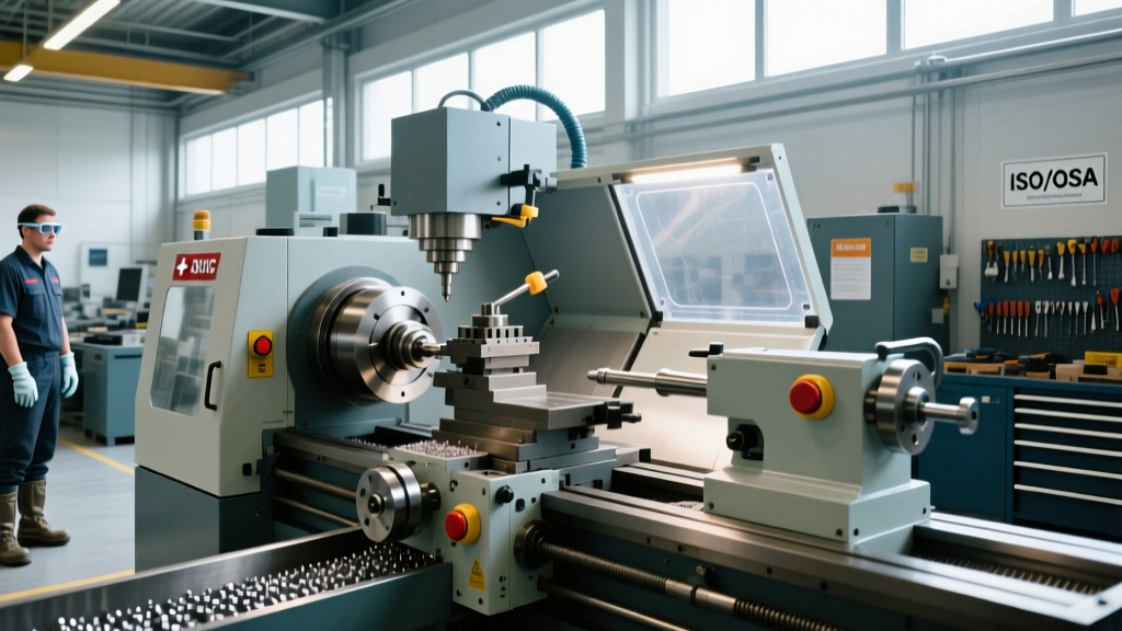
Unlike conventional CNC lathes where the cutting tool traverses the Z-axis to remove material from a stationary or rotating workpiece, Swiss machine tooling relies on a sliding headstock architecture. The bar stock is clamped in the main spindle collet and fed axially (Z-axis) through a stationary guide bushing, while the turning tools remain fixed in the Z-axis and only move radially (X-axis) to engage the material. This fundamental kinematic inversion is what allows Swiss-type lathes, such as the Citizen Cincom L32 or Tsugami B038 series, to machine extremely long, slender parts with sub-micron precision.
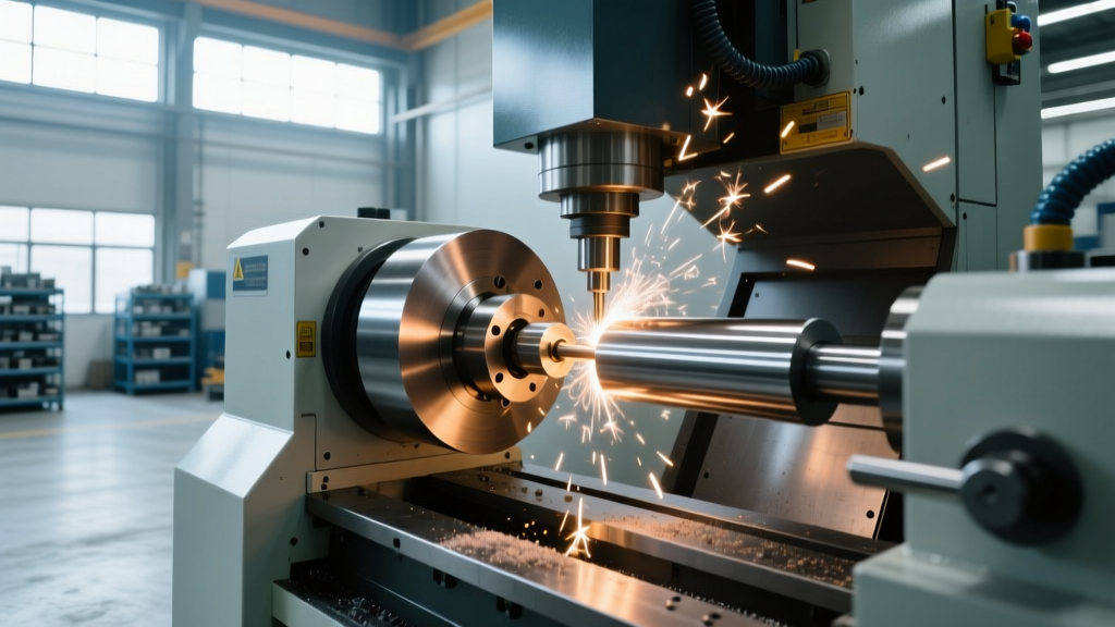
By positioning the cutting tools within 1 to 3 millimeters of the guide bushing's exit point, the bending moment applied to the workpiece is virtually eliminated. In a standard lathe, extending a 0.250-inch diameter part 2 inches unsupported will result in severe deflection and chatter. In a Swiss-type configuration, that same part can be machined continuously as the headstock feeds the material through the bushing, maintaining rigid support up to the exact point of cut.
⚠️ CRITICAL WARNING: Bar Stock Surface FinishA common and catastrophic mistake in Swiss machining is using peeled or turned bar stock instead of centerless ground stock. The longitudinal feed marks left by peeling act like a file against the carbide guide bushing, destroying the bushing's internal tolerance in a matter of hours. Always specify h6 tolerance centerless ground bar stock for standard carbide bushings. If your application requires peeled stock to reduce material costs, you must upgrade to a specialized roller-type guide bushing system (such as those manufactured by FMB) which uses rotating rollers instead of a static carbide sleeve to support the bar.
Guide Bushing Specifications and Material Science
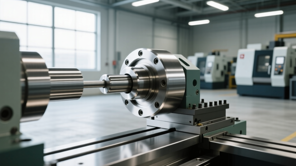
The guide bushing is the defining component of Swiss machine tooling. It dictates the concentricity, surface finish, and dimensional accuracy of the final part. Modern guide bushings are typically manufactured from micro-grain tungsten carbide to resist the extreme abrasive wear generated by high-speed bar feeding. The internal bore is honed to a mirror finish (Ra 0.1 µm or better) to minimize friction.
Clearance between the bar stock outer diameter (OD) and the bushing inner diameter (ID) is the most critical setup variable. Too tight, and the bar will bind, causing feed motor alarms and poor surface finish; too loose, and the part will vibrate, resulting in out-of-roundness and tool breakage.
| Workpiece Material | Bar OD Range | Recommended Total Clearance | Bushing Type |
|---|---|---|---|
| Free-Machining Steel (12L14) | 0.125" - 1.000" | 0.0002" - 0.0004" | Fixed Carbide |
| Stainless Steel (303/304) | 0.125" - 1.000" | 0.0003" - 0.0005" | Fixed Carbide |
| Aluminum (6061-T6) | 0.125" - 1.250" | 0.0005" - 0.0008" | Fixed Carbide / Steel |
| Engineering Plastics (PEEK/Delrin) | 0.125" - 1.000" | 0.0010" - 0.0020" | Fixed Steel / Bronze |
Gang Slide Architecture and Live Tooling Integration
Swiss machine tooling relies heavily on gang slides—linear tool posts that mount multiple turning and live tools in a single row. This eliminates the indexing time associated with traditional turrets, allowing for rapid tool changes measured in milliseconds rather than seconds. Modern 5-axis Swiss machines integrate a main gang slide for OD turning, a secondary back-working tool post for sub-spindle operations, and cross-drilling units for Y-axis and radial features.
The integration of live tooling has evolved significantly. Older Swiss machines relied on VDI (DIN 69880) interfaces, which often suffered from runout and lacked rigidity for heavy milling. The current 2026 standard for high-end Swiss lathes is the BMT (Base Mount Tooling) interface. BMT toolholders bolt directly to the gang slide with a large coupling gear, reducing runout to less than 3 microns and increasing radial rigidity by up to 40%, which is essential when using live tooling to mill flats or drill cross-holes in hardened medical implants.
Synchronous vs. Independent Spindle Operations
When transferring a part from the main spindle to the sub-spindle for back-working, the C-axes of both spindles must be perfectly synchronized to prevent torsional stress or part deformation. On Fanuc-controlled Swiss machines, this is achieved using spindle synchronization G-codes (such as G114). The sub-spindle matches the exact RPM and angular phase of the main spindle before the transfer collet closes. Advanced tooling setups utilize independent C-axis contouring on the sub-spindle to helical-interpolate complex internal geometries while the main spindle continues roughing the next part, maximizing machine utilization.
"The true bottleneck in Swiss machining is rarely the cutting speed; it is chip evacuation in deep-cavity back-working. If your sub-spindle tooling does not feature directed through-tool coolant, you are leaving 30% of your cycle time on the table clearing chips with peck cycles."
— Senior Manufacturing Engineer, Medical Device Contract Manufacturer
High-Pressure Coolant Delivery Systems in Swiss Turning
Standard 300 PSI flood coolant is entirely inadequate for the micro-tooling used in Swiss machining. When drilling holes smaller than 2.0mm (0.080"), the flute volume is too small to carry chips out of the cut using low-pressure fluid. Implementing a high-pressure coolant (HPC) system operating between 1,500 and 3,000 PSI is mandatory for reliable micro-drilling and deep-hole gun-drilling operations.
For Swiss machine tooling, coolant delivery must be precisely targeted. Systems like those from Sandvik Coromant utilize nozzle geometries that create a high-velocity wedge of fluid, breaking chips at the shear zone before they can wrap around the tool or score the workpiece bore.
Setup Protocol: Micro-Drilling with HPC (1,500+ PSI)- Verify Toolholder Seals: Ensure all VDI/BMT live toolholders and ER collets are equipped with O-ring coolant seals. Standard collets will leak 90% of the pressure at the spindle face.
- Install Filtration: HPC pumps require 10-micron or finer filtration. A single 50-micron chip will instantly clog a 0.3mm drill's internal coolant hole, causing immediate tool failure.
- Program Chip-Breaking Pecks: Even with HPC, program a peck cycle (G83) with a retract distance equal to 1.5x the drill diameter to allow the high-pressure jet to flush the flutes completely.
- Monitor Pressure Drops: Use the machine's PLC macro variables to monitor real-time coolant pressure. A sudden pressure spike indicates a clogged tool; a pressure drop indicates a broken tool or blown seal. Map these to M00 (stop) commands.
Tooling Selection Framework for Micro-Machining
Selecting the correct insert geometry for Swiss turning requires balancing sharpness with edge strength. Because the depth of cut (DOC) in Swiss finishing passes is often under 0.005", standard negative-rake inserts will push the material away rather than shear it. You must select positive-rake, highly polished inserts designed specifically for Swiss-type lathes.
- Roughing (Steel/Stainless): Use a CVD-coated insert with a reinforced edge hone (e.g., 0.0004" T-land). Look for grades like Sandvik's GC4325 or Kyocera's PR1225 for high heat resistance.
- Finishing (Non-Ferrous/Plastics): Uncoated, mirror-polished micro-grain carbide inserts with a razor-sharp edge (0.0000" hone). These prevent material smearing and built-up edge (BUE) on aluminum and PEEK.
- Threading: Full-profile, lay-down threading inserts are preferred over V-notching to eliminate the need for secondary deburring operations, which is critical when parts are caught in the sub-spindle and cannot be manually accessed.
FAQ: Edge Cases in Swiss Tooling
Why does my guide bushing keep scoring when machining titanium?
Titanium alloys (like Ti-6Al-4V) have a high affinity for carbide, leading to micro-welding and galling inside the guide bushing. When machining titanium on a Swiss lathe, you must use a specialized guide bushing with a proprietary anti-friction coating (such as TiN or DLC) and reduce the bar feed pressure. Additionally, ensure the bushing clearance is increased by 0.0002" to account for the thermal expansion of the titanium bar during heavy roughing cuts.
Can I use standard lathe boring bars in a Swiss sub-spindle?
While physically possible if the shank diameter matches, standard boring bars lack the necessary overhang-to-diameter ratio optimized for Swiss back-working. Swiss-specific micro-boring bars (like those from Tsugami or Eppinger) feature solid carbide shanks or heavy-metal (tungsten alloy) bodies to dampen harmonic vibrations in deep, small-diameter bores. Using a standard steel shank bar in a 4mm bore will almost certainly result in severe chatter and poor surface finish.