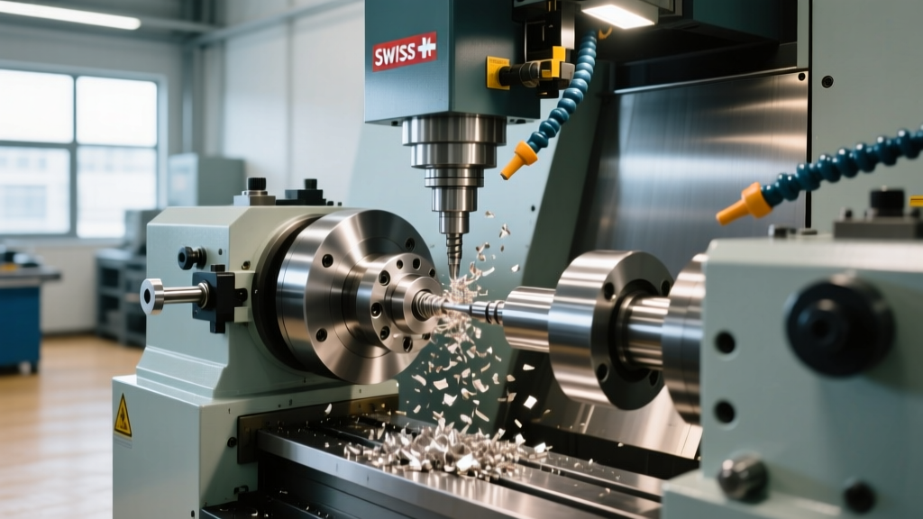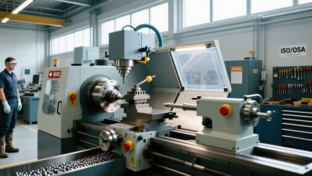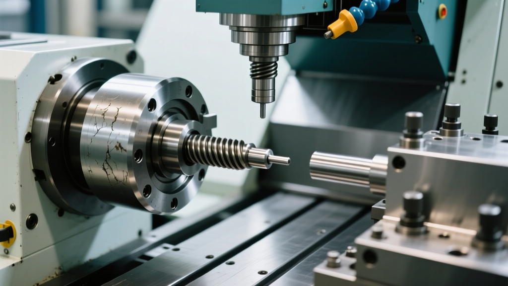
How Does a Lathes CNC Machine Work? Technical Specs
Explore how a lathes CNC machine works with deep technical specs, spindle mechanics, axis configurations, and real-world operational parameters.
Decoding the Kinematic Architecture
The term 'lathes cnc machine' often encompasses both standard 2-axis turning centers and complex mill-turn platforms. At the foundational level, the X-axis controls the cutting tool's radial depth of cut, while the Z-axis governs the longitudinal feed along the workpiece. However, advanced manufacturing requires interpolating additional axes to eliminate secondary operations.
Multi-Axis Configurations and C/Y Integration
Adding a C-axis transforms the main spindle into a controllable rotary axis. This allows for precise angular positioning (often down to 0.001-degree increments) and enables rigid tapping, drilling, and milling directly on the part's face or periphery. When a Y-axis is introduced, the tool can move perpendicular to the X-Z plane, unlocking off-center milling capabilities. According to Mazak's Multi-Tasking Machine Architecture documentation, integrating a Y-axis with a B-axis (tilting spindle head) on a 9-axis platform allows for simultaneous 5-axis contouring, effectively merging the capabilities of a CNC lathe and a 5-axis vertical machining center into a single chucking.
Spindle Drive Mechanics and Torque Delivery
The spindle is the heart of the turning center. Traditional belt-driven spindles suffer from micro-slip, vibration at high RPMs, and thermal expansion from the belt housing. The 2026 industry standard for mid-to-high-tier machines is the Built-In Motor (BIM) spindle.
- Belt-Driven Spindles: Max RPM typically capped at 4,000–6,000. High peak torque but poor surface finish capability at high speeds due to harmonic vibration. Cost-effective for heavy roughing of large-diameter forgings.
- Direct-Drive / BIM Spindles: The rotor is integrated directly onto the spindle shaft. This eliminates transmission losses, reduces thermal displacement to under 5 microns, and allows RPMs of 12,000 to 20,000+. BIM spindles deliver 100% of their peak torque (e.g., 300+ Nm) at near-zero RPM, which is critical for interrupted cuts and heavy milling operations via live tooling.
'Selecting the correct spindle torque curve is more critical than maximum RPM. A machine with 400 Nm of torque at 500 RPM will outperform a 12,000 RPM spindle with only 80 Nm of low-end torque when machining high-tensile alloys like Inconel 718.' — Advanced Manufacturing Tooling Guidelines, Sandvik Coromant.
Guideway Technologies: Box Ways vs. Linear Guides
The structural interface between the machine base and the moving saddles dictates damping capacity, rapid traverse rates, and heavy-cut stability. Engineers must select the guideway system based on the specific material removal rate (MRR) requirements.
| Feature | Box Ways (Sliding Friction) | Linear Guideways (Rolling Friction) |
|---|---|---|
| Friction Coefficient | ~0.05 (requires specialized lubrication) | ~0.003 (recirculating ball/roller bearings) |
| Damping Capacity | Exceptional; absorbs high-frequency chatter | Moderate; prone to chatter on interrupted cuts |
| Rapid Traverse Rates | 15 – 20 m/min | 30 – 45 m/min |
| Best Application | Heavy roughing, titanium, cast iron, deep boring | High-speed finishing, aluminum, high-volume production |
| Maintenance Profile | Requires periodic scraping and Turcite-B replacement | Sealed cartridges; replace entire block when worn |
Turret Rigidity and Live Tooling Dynamics
The turret holds the cutting tools and dictates tool-change speeds and milling rigidity. The industry has largely transitioned from VDI (DIN 69880) tooling interfaces to BMT (Base Mount Turret) systems for machines requiring live tooling.
In a VDI system, the tool holder is clamped via a radial or axial serrated coupling. While quick to set up, the overhung nature of VDI holders introduces leverage that reduces rigidity during heavy milling. BMT systems mount the tool holder directly to the turret face using a large-diameter curvic coupling and high-strength clamping bolts. This configuration increases torsional rigidity by up to 300%, allowing live tooling to take radial depths of cut (DOC) exceeding 3mm in steel without deflection. Modern BMT turrets utilize internal servo motors rather than external gearboxes, enabling tool-to-tool change times of 0.2 seconds or less.
Market Segmentation and 2026 Technical Tiers
Capital equipment buyers must align machine specifications with production volume and part complexity. Based on current Haas Automation and broader market pricing models, CNC lathes segment into three distinct technical tiers.
| Machine Tier | Typical Price Range (2026) | Spindle & Axis Specs | Target Production Environment |
|---|---|---|---|
| Entry-Level 2-Axis | $85,000 – $135,000 | 4,000 RPM Belt Spindle, 2-Axis, VDI Turret | Job shops, simple shafts, secondary op finishing |
| Mid-Range Mill-Turn | $180,000 – $320,000 | 10,000 RPM BIM, C/Y-Axis, BMT Turret, Chip Conveyor | High-volume automotive, aerospace fittings, medical |
| High-End Multi-Task | $450,000 – $950,000+ | 20,000 RPM Electro-Spindle, B-Axis, Lower Turret, Tailstock | Complex aerospace, titanium implants, done-in-one parts |
Control System Look-Ahead and Interpolation
The mechanical hardware is only as effective as the CNC control driving it. Modern controllers like the Fanuc 31i-B or Siemens Sinumerik 840D sl utilize nanometer-level interpolation and advanced look-ahead functions. A standard 200-block look-ahead allows the control to calculate deceleration and acceleration vectors well before the tool reaches a sharp corner, preventing dwell marks and maintaining constant surface cutting speeds (CSS). For complex mill-turn contouring, look-ahead capacities exceeding 1,000 blocks are mandatory to ensure smooth kinematic transitions and prevent axis servo lag, which directly impacts surface finish Ra values.
Operational Decision Framework
When specifying a new turning center, utilize this rapid decision matrix to avoid over-investing in unused capabilities or under-specifying critical rigidity:
- Is the part family primarily rotational with minimal off-center features? Specify a high-rigidity 2-axis box-way machine with a heavy-duty tailstock. Skip the Y-axis and live tooling to maximize structural damping and lower capital costs.
- Do parts require complex prismatic milling and tight concentricity? Mandate a mill-turn platform with a BMT turret, C/Y axes, and a BIM spindle. The elimination of secondary milling operations will offset the 40% higher machine cost within 14 months of production.
- Are you machining long, slender shafts (>10:1 L/D ratio)? Prioritize a machine equipped with a programmable servo tailstock and integrated steady-rest capabilities. Standard hydraulic tailstocks lack the dynamic thrust control required to prevent bowing during high-speed finishing passes.
Understanding the precise mechanical and electronic specifications of these platforms ensures that shops invest in equipment that matches their exact metallurgical and geometric requirements, maximizing spindle utilization and minimizing cost-per-part.